OR WAIT null SECS

© 2024 MJH Life Sciences™ and Turbomachinery Magazine. All rights reserved.
Applying hermetically sealed compressor to sour and corrosive gases
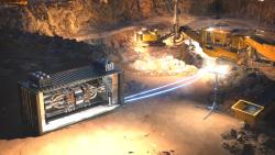
Siemens STC-ECO compressor[/caption]
For an upstream gas processing facility in Saudi Arabia, a 5.8 MW unit capable of handling sour and corrosive gases was developed by adapting a hermetically sealed compressor.
The process gas is saturated hydrocarbon gas separated from crude oil. Its composition varies significantly over the plant’s production life, and expected to contain considerable amounts of wet CO2 in combination with H2S and water vapor. This means that materials used for the motor-compressor have to withstand corrosive gas. The hermetically sealed compressor contains a single shaft for both the motor and compressor section, hence the rotor and thrust disk need to be manufactured from corrosion-resistant materials.
This article contains excerpts from the paper, “Adapting hermetically sealed compressor technology to deal with sour and corrosive gases” by Marcel Buse, Mark Van Aarsen of Dresser-Rand, part of Siemens Oil and Gas and Eyad Al-Khateeb and Bader Al-Jughaiman of Saudi Aramco presented at the 2016 Turbomachinery Symposium.
However, a major drawback of these materials is their low iron-content, hence they are not suitable for an efficient electric motor rotor and magnetic bearing thrust disk. In addition, the electrical insulation systems of motor stator windings and active magnetic bearing stator windings have to withstand the corrosive attack whilst allowing cooling media to extract heat generated because of electrical losses.
Therefore, the major design challenges for upstream gas compression applications are condensed to the following questions:
• How to solve the two contradictory functions of an hermetically sealed rotor and thrust disk: sour and corrosion resistant &
good magnetic properties?
• How to solve the two contradictory functions of the separation ‘can’ of the motor stator: sour and corrosion resistant & nonconductive?
In order to distinguish clearly defined areas of application and their associated material selection, a category definition was set focusing on application temperature, H2S content, CO2 partial pressure and the amount of Chlorides and gas humidity. Upstream gas process parameters clearly mandate material selections for Category 3 'Sour and Corrosive'. This category is more complicated as opposed to Categories 1 and 2 and dictates the use of advanced designs for the shaft and thrust disk.
The electrical insulation properties of the gas depend on the composition and pressure. It is well known that water vapor has harmful effect on the insulation properties. Gas molecules which will dissociate easily forming ions are also harmful to electrical properties. It is therefore not advisable to allow process gas to enter the stator windings. Further, the corrosion resistance of copper is a function of fluid velocity. Corrosive attack is accelerated by dissolved oxygen, carbon dioxide and or ammonia. Copper and copper-based alloys are resistant to neutral and slightly alkaline solutions, dry gases, natural gas, and most other hydrocarbons. They are attacked by hydrogen sulfide and other sulfur compounds, most acids and strong alkalis, ref (4), (5). The process gas in the upstream
application contains H2S which will react with copper bars of the rotor as well as copper windings in the stator.
The stator copper windings are insulated using insulating material. However it is not impermeable to gas and susceptible to high levels of corrosion with H2S. Effect of H2S and CO2 on high voltage insulation materials was extensively studied by Sihvo, ref (5). His findings were that PET film insulation cannot withstand raw natural gas. Insulations based on epoxy resins reacted with water vapor over a period of time leading to degradation. H2S also contributed to this degradation. All these factors contribute to the primary concept to avoid electrical
windings being exposed to process gas for upstream applications. This also meant that the stator windings could not be cooled by circulation of process gas. And as there should be no need for external clean gas supply, the stator windings are cooled with a liquid in a closed loop circuit.
Separating the electrical motor stator windings from the process gas is achieved by a specially designed thin-walled 'can' in the air gap of the motor. One of the main and most challenging design requirements was that the used material for the can should be electrically non-conductive in order to avoid excessive heat generation developed by eddy current losses in the strong motor magnetic field. This eliminated the possibility to use metal alloys or even carbon-fire reinforced polymers. After extensive qualification and testing the solution was found by using a special glass-fiber reinforced polymer (GFRP). A further requirement was to limit the wall thickness of the can. This would otherwise have a detrimental effect on motor power factor which would result in poor electrical effectiveness. The final can wall thickness achieved was 5.5 millimeters and allows a limited differential pressure over this cylindrical
component. In order to achieve the full design pressure of the prototype unit of 150 barg, the pressure of the cooling system fluid of the motor stator modulates with the suction pressure by means of a simple piston-style compensator. In normal operation and as a result of smart selection of the pressure reference points, the fluid pressure of the insulation oil is slightly higher than the internal process gas pressure, thus avoiding any pressure induced migration of process gas into the closed liquid cooling system.
Separating the high speed rotor was achieved by adopting an advanced solid rotor design instead of rotor laminations. The squirrel cage is formed by copper bars and short circuit rings that are integrated in the rotor by means of hot isostatic pressing (HIP). All copper is then protected from the process gas by means of a corrosion and erosion resistant alloy cladding. Separating the Active Magnetic bearing stator windings and sensors from the process gas is achieved by applying a thin sheet of metal welded to the bearing bracket. The pressure load on the thin sheet is supported by the stator bearing internal structure. The bearing cavities are atmospheric and cooling is arranged through heat conduction to the integral bearing bracket and housing or with additional cooling jacket around the bearing as part of the integral motor cooling system.