OR WAIT null SECS

© 2024 MJH Life Sciences™ and Turbomachinery Magazine. All rights reserved.
Gas turbine failure due to wrong design of waterwash system
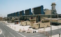
Abdulmajeed A. Ali of Saudi Aramco presented a case study on gas turbine failure due to an improperly designed waterwash system at the ASME/IGTI show this year in Vancouver. Here's a snapshot of the presentation.
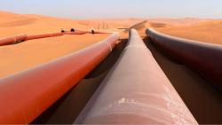
A new compressor water wash system was introduced to recover the turbine performance loss in the cogeneration plant. The new water wash system consists of piping connection on the base, two motor operated water injection valve (MOVs), and the appropriate spray manifold for ON-LINE/OFF-LINE process. Drains from the inlet plenum, combustion area, exhaust frame, and the exhaust plenum are also provided.
The system works at a rated water pressure of 100 Psi (7 bar) at rated flow of 10 GPM (38 Ltr/min). The nozzles spray water at temperature between 65 – 180 F (18 – 82 C). On the other hand, the off-line water wash system consist of only 7 spray nozzles at rated pressure of 85 Psi (6 bar) and rated flow 42 GPM (159 Ltr/min) at same temperature.
Cross firing tube broken by quenching White scale patterns sprayed on the t-piece
The compressor water wash system was commissioned recently and found the main water wash system MOV’s configuration (MOV-20TW-1: Offline compressor water wash motor valve and MOV-20TW-3: Online compressor water wash motor valve) was swapped, causing the off-line compressor water wash to be activated instead of the online compressor water wash and via versa. This observation was followed by the immediate shutdown action of compressor water washes system until proper correction with the aid of the vendor (GE). The compressor water wash system was recommended by GE – because of the system’s advantage in fouling deposit removal from compressor components - to maintain equipment efficiency, power output and reduce corrosion rat
Improper MOV configuration led to a large volume water supply to the compressor and combustion chamber while the turbine unit was in the operating mode, and the isolation valve of the air extraction pipe was lined up in the open position, while all drain lines were lined up in a closed position (correct line up in the operating mode). This made water strike the cross firing tubes that were extremely hot, causing quenching of the material and sudden shock cooling, resulting in material fracture. The fracture material flowed with the exhaust stream, hitting turbine buckets/nozzles and magnifying damage that lead to more fracture material from the turbine buckets and nozzles.
A massive amount of water flowed from the air extraction pipe to the heater-less dryer skid system, with the aid of the pressurized air from the compressor (120 psig and 670 0F). This influx resulted in dissolving the desiccant in the dryer tower tank vessel and blocking the dryer downstream skid valves. This blockage trapped air in the dryer system under positive pressure.
While the turbine unit was under shutdown mode (proper interlock configuration of compressor water wash MOVs with GE support) the dissolved desiccant flowed back to the combustion chamber since the pressurized air from the compressor was neutralized to atmospheric pressure, and positive pressure in the heater-less dryer skid system aided the flow route.
After successful MOV configuration - with proper commissioning and verification of the compressor water wash system to satisfactory results - the trapped dissolved desiccant in the combustion chamber was forced to flow. The desiccant moved with the pressurized air stream, along with the combustion chamber components, during the startup of the turbine unit (operating mode); since the contaminated desiccant solidified in the air extraction line. The flowed contaminated desiccant dried in the combustion chambers component and was subjected to extreme heat flux. The result was blocked air cooling passes, causing overheat (burnout) and melting of some combustion chamber components and first stage turbine nozzles.
The investigation committee studied the case and found white scale in the combustion chamber and in the air extraction line and drain lines. This scale was the same material used in the air dryer towers tanks vessel (desiccant activated alumina used to extract humidity from the compressed air, as part of the air dryer skid system). Samples studied by the laboratory and confirmed the material match.
The observed damage found in the turbine Hot Gas Path components resulted due to improper instrumentation interlock configuration and lack of quality commissioning checklist - between the online/offline compressor water wash motor operated valve - in addition to the lack of proper air dryer maintenance procedure, which resulted in a costly repair (material and manpower) within a timeframe of one month.
Below are the lessons learned from the failure.
- The quality of commissioning and start-up check lists is important to ensure smooth and safe operation process.
- Install permanent non-return valve at the air extraction line.
- Conduct appropriate periodic preventive maintenance of the Heater-less Air Dryer System.