OR WAIT null SECS

© 2024 MJH Life Sciences™ and Turbomachinery Magazine. All rights reserved.
Gas turbine selection: Heavy frame or aeroderivative
Optimum gas turbine selection can be done after good comparison of the different types of turbines There are variations between aeroderivative and heavy frame industrial gas turbines including weight, size, efficiency, design, bearing type, and lubrication oil system.
Heavy industrial frame or aero-derivative
Heavy frame industrial gas turbines compared to aeroderivative gas turbines are usually slower in speed, narrower in operating speed range, heavier, larger, have higher air flow, slower in start-up and need more time and spare parts for maintenance. Heavy frame industrial gas turbines use hydrodynamic bearing.
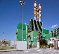
A heavy duty gas turbine (GE 10, left) and an aeroderivative LM6000.
Aeroderivative gas turbines use anti-friction bearing. Advanced aircraft engine and space technologies have been used to provide maintainable, flexible, light weight and compact aeroderivative gas turbines. The key to maintainability is the modular concept which provides for removal of components and replacement without removing the gas turbine from its support mounts.
The heavy frame industrial units, by contrast, require more amount of effort to remove and replace components (especially combustor parts) and more effort to inspect or repair the sections. The user should weigh needs and requirements against the variety of gas turbines offered. Traditionally, preference has been to place the aeroderivative units in remotely located applications (including offshore) and to place heavy frame industrial units in easily accessible base-load applications. The heavy frame industrial gas turbines consume more fuel and more air than the aeroderivative units. They are exposed to a greater quantity of the contaminants in air that cause corrosion.
Today aeroderivative gas turbines offer 10-15% more efficiency compared to heavy frame industrial type gas turbines. Some engineers predict aeroderivative gas turbines may replace traditional heavy frame industrial type gas turbines in the future!
Hot end or cold end drive
In a hot end drive configuration the output shaft is at the turbine end where exhaust gas can reach high temperatures and it may affect bearing operation and life. Also, it may be difficult to service the unit as the assembly must be fitted through the exhaust duct. Constraints of the hot end drive: output shaft length, high temperature, exhaust duct turbulence, exhaust duct pressure drop and maintenance accessibility. Insufficient attention to any of these details often results in power loss, vibration, shaft (or coupling) failure and increased down-time for maintenance.
In the cold end drive configuration the output shaft extends out the front of the air-compressor. Here the driven equipment is accessible, relatively easy to service, and is exposed to ambient temperature only. Drawback: air-compressor inlet must be configured to accommodate the output shaft and the driven equipment. This inlet duct must be turbulent free and provide vortex free (uniform) flow throughout the operating speed range. The problem resulting from a poor design could be catastrophic, for example, inlet turbulence can induce surge in air-compressor resulting in complete destruction of the unit. However, inlet duct turbulence could often be eliminated at the expense of pressure drop. In modern gas turbine applications “hot end drive” is usually used.
Single-spool or multi-spool
Single-spool integral-output-shaft gas turbines (both hot end drive and cold end drive) are used primarily to drive electric generator. The integral shaft gas turbine is uncommon for mechanical drive applications. The high torque required to start pumps and compressors under full pressure results in high turbine temperature during the start-up cycle when cooling air flow is low or non-existent. Integral shaft gas turbine may only be used in very large LNG compressor trains (such as Frame 7 or Frame 9, using helper/start electric motor).
A split output shaft gas turbine could be considered as a single spool gas turbine driving a free power turbine. The air-compressor-turbine shaft (air-compressor and its turbine shaft assembly) is not physically connected to the power turbine shaft, but they are coupled aerodynamically. This makes starting easier in mechanical drive. It is usually referred to as “split shaft mechanical drive gas turbine”. It could attain self sustaining operation before it picks up the load of the driven equipment. The power turbine can be designed to operate at the same speed as the driven equipment and eliminate the need for a gearbox (typical gearbox losses are 2-5%). This design is limited to the hot end drive configuration. In dual spool split output shaft gas turbine, independent low and high pressure air-compressors and turbines generate the hot gases that drive the free power turbine.
Amin Almasi
Amin Almasi is senior rotating equipment consultant in Brisbane, Queensland, Australia.
Email: amin_almassi@yahoo.com, amin.almasi@worleyparsons.com