OR WAIT null SECS

© 2024 MJH Life Sciences™ and Turbomachinery Magazine. All rights reserved.
ONE TEST IS WORTH 1,000 EXPERT OPINIONS
FUNCTIONAL TESTING OF GE GAS TURBINES MUST BE DONE AFTER MODIFICATIONS
By David Lucier
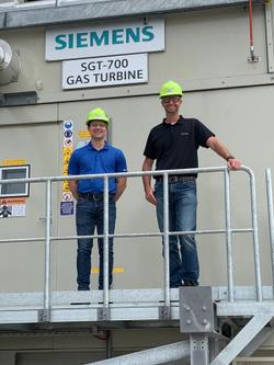
Figure 1: Simulating GT start-up using the GE Speedtronic Calibrator.
Suppose you are charged with making a modification to an existing GE gas turbine (GT). When completed, it should function better than it did during previous operation. Better yet, operation should be significantly improved. Otherwise, why bother?
All too often after a change is made, other problems arise. These issues should never be a result of negligence on the part of those charged with the responsibility of upgrading the unit.
At GE, there is a group called Conversions, Modifications and Upgrades (CMU). It offers gas turbine owners/operators (GT O/O) opportunities to make changes aimed at improving operation, increasing reliability or upgrading performance. GT O/O bases its actions on technical information letters (TIL) and field modification instructions (FMI). These documents and others (starting with the letters GEK or GER) are usually the catalysts for changes and improvements.
Performance and reliability
Certainly, many modifications can and do boost performance and reliability. But it would be wise to heed a principle I learned back as a trainee on the GE Gas Turbine Start-up Program (GTSP) from the late engineer George Kennedy: Always functionally test a GT after making a change.
While this may seem obvious, testing before restarting the GT is not always done. The smart way to look at it is that even if the turbine was malfunctioning before a change was made, the original GE design and operation must have once worked properly. My former partner, the late Charlie Pond, advocated “baby steps,” as you bring a GT back online.
Based on experience, anyone upgrading a turbine should test, check and simulate before returning a GT to full operation. For early Speedtronic Mark I and II GTs, for example, the GE Calibrator device was used to calibrate the panel. It can also be used to simulate operation. You can “dummy in” such signals as turbine speed (NHP), average turbine exhaust temperature (TTX) and voltage to a transducer for the intervalve gas fuel pressure (P2). This enables the engineer to simulate the operation of the turbine while still at rest (Figure 1).
Once adequately tested, checked and simulated after a TIL or FMI change, there are a few cautions worth heeding during start-up. Use audio communications with someone placed at the turbine panel ready to push the 5E emergency trip push button in case trouble is detected. Also, when out on the turbine deck and firing the turbine, have someone near the hydraulic dump valve with earphones, so a trip signal can immediately shut off the fuel supply.
Finally, use your human senses: Look, listen, smell and touch (fortunately, tasting is never necessary). Substitute it with a sixth sense, which could be called intuition. Never assume anything is right until you prove to yourself that the GT is safe to operate.
Let us look at a typical upgrade: Conversion to a new liquid fuel system recommended by GE. This includes going from a variable-displacement fuel pump to a fixed displacement concept. Doing so would require a new flow divider having a 60-tooth wheel and speed pickups. These are needed for fuel flow feedback in a closed loop control system.
The MS5001N machine had an original Roper flow divider installed on a MS5001N. It had rigid tubing for the ten flow elements, as well as pressure taps that go to the selector valve and pressure gage. However, special braided high-pressure hoses are used with the new flow divider installed during the upgrade. Flexible hosing eliminates any stresses on the new flow divider due to mismatching of tubing connections.
Roper flow dividers require installation in a strain-free condition. The system was bled of air. A digital voltmeter was used to measure fuel flow when testing. GE does not manufacture the fuel pumps, flow dividers or bypass valves with servo drives. These products come from vendors, such as OilGear, NY Airbrake and Roper. They are connected in the field for the first time by the crew doing the modification.
Liquid fuel pumps from the OEM OilGear are often converted from variable displacement to positive displacement, eliminating the hydraulic servo mechanism on top and installing a servo-operated bypass valve. In so doing, have the fuel pump serviced, since it might be nearly 50 years old. When installing the refurbished pump, it is vital to temporarily “block open” the fuel stop valve and put the unit on ratchet so the system can be properly filled with oil and then bled. With these types of piston pumps, the fuel flowing through the system also acts as a lubricant for the bearings, seals and pistons.
Necessary evil?
Testing the gas turbine after modifications should not be looked at as a necessary evil. It should be a desirable confirmation that conversion work was successful, before firing the turbine. If the pump is refurbished as suggested, care should be taken to return it to operation and confirm its viability.
These modifications involve a new bypass valve, that subtracts some of the fuel heading for the combustors by recirculating some of the flow to the suction side of the pump. But it is vital to confirm that the new servo device is correctly wired (to open and close the fuel valve as intended). If wired incorrectly, excess fuel to the combustors could overfire the gas turbine. This could be catastrophic.
Tests and simulations do not typically take more than a day or two, but are vital to assure that this axiom is confirmed: A test is worth 1,000 expert opinions.
Author: David Lucier, Owner and General Manager, Pond and Lucier, LLC (PAL). For more information, visit www.pondlucier.com, email: dlucier@pondlucier. com or call 518 371-1971