OR WAIT null SECS

© 2024 MJH Life Sciences™ and Turbomachinery Magazine. All rights reserved.
Using accelerometers on gears
Accelerometers are commonly used on high speed gear units that are built according to API 613. But the use of the signals from the accelerometers is very often subject to discussion.
Should the accelerometer signal be used as acceleration or velocity?
Should trip points be based on RMS (Root Mean Square) or 0-peak values?
What frequency range should be analyzed?
What values should be used for the alarm and trip set points?
There are no general answers to these questions. Especially for acceleration signals, the choices are complex and need to be analyzed case by case.
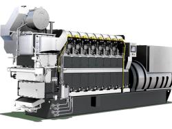
Single-helical with thrust collar[/caption]
This article contains excerpts from “High frequency vibrations on gears” by Dietmar Sterns of Renk AG and Michael Elbs of ISMB Dautermann at the 2017 Turbomachinery Symposium
When casing vibrations are measured on gear units, first decide between measuring velocity or measuring acceleration. Velocity should be measured in the frequency range of 10 Hz to 1000 Hz and displayed as an RMS value (refer to ISO 10816). Acceleration should be measured in the frequency range up to 10000 Hz and displayed as a 0-peak value.
By measuring velocity, low frequency vibrations are monitored – similar to the shaft vibrations. This allows detecting issues like unbalance, misalignment, oil whirl, etc.
Velocity signals can be used for machinery protection, condition monitoring and/or machinery diagnosis. Measuring acceleration is recommended to monitor high frequency vibrations like vibrations close to the gear mesh frequency. Acceleration measurement can help in condition monitoring and machinery diagnosis, but is not recommended for machinery protection.
To be able to use the acceleration signal for condition monitoring, it is necessary to: - Record the vibration baseline data during a loaded test (if such test is performed) and during commissioning. To record the baseline completely, vary the speed and power over the whole specified range or at least over the expected operating range.
Store the baseline data. This is the vibration signature of the gear unit in new, undamaged condition and is going to be used as a reference for any vibration data that will be recorded later, during operation.
Compare any acceleration values measured during operation with the baseline value recorded at the same operating conditions (speed, power, lube oil pressure, lube oil temperature).
If the total acceleration value recorded during operation shows a strong increase related to the baseline data recorded at the same operating conditions, then the vibration data should be investigated in detail. Ask the OEM and/or a specialist on machinery diagnosis for support.
In general, do not use the total value of the acceleration signal for machinery protection, i.e. for triggering a trip signal. However, the total value of the acceleration signal can be used for machinery diagnosis. It may be used to trigger an alarm, but the alarm value should depend on operating parameters such as speed and power. This variable alarm value should be set in accordance with the baseline values. The value of the acceleration signal in terms of condition monitoring can be increased by applying frequency filters on the acceleration signal, so that only the frequency band of interest is monitored. For example, a frequency band around the gear mesh frequency may be monitored.
For fixed speed applications, this can be achieved quite easily, as the frequency filters can be set to constant values. For speed variable drives, the limit values of the frequency filters need to be proportional to the speed. More complex evaluation methods of the acceleration signal could increase further its value for condition monitoring. Such methods exist and are already in application for roller bearings. For gears they need to be developed respectively to be integrated into monitoring systems.