
|Articles|September 15, 2017
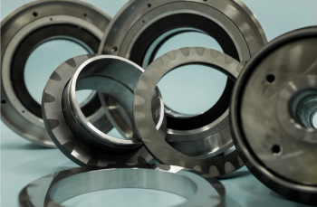
Open and closed compressor impellers
Author(s)William Forsthoffer
Advertisement
Some open impellers can operate at higher tip speeds, and thus produce greater head than closed impellers. Open impellers can produce approximately 4,500 – 7,500 m-kg force/kg mass ( 15,000-25,000 ft-lbs force/lb mass) of head per stage. This is because a side plate is not attached to the inlet side of the vanes, which results in significantly lower blade stresses. The disadvantages of open impellers are their lower efficiency, due to increased shroud (front side) leakage and increased number of blade natural frequencies resulting from the cantilevered attachment of the blades to the hub.
Most end users restrict the use of open impellers to plant and instrument air applications, since the high speeds and intercooling offset the efficiency penalties caused by shroud leakage. Older designs of multistage centrifugal compressors frequently used open impellers in the first stages, since the high flows caused unacceptable side plate stresses in closed impeller design. Modern calculation (finite elements) methods and manufacturing methods (attachment techniques – machine welding, brazing, etc.) now make possible the use of enclosed first stage impellers for all multistage compressor applications. Finally, radial bladed impellers (whether open or enclosed) produce an extremely flat (almost horizontal) head curve.
This characteristic renders these impellers unstable in process systems that do not contain much system resistance. Therefore, radial impellers are to be avoided under these circumstances (plant and instrument air compressors, charge gas, compressors and refrigeration applications with side loads).
Enclosed impellers
Note that the first stage impeller in any multistage configuration is always the widest. That is, it has the largest flow passage. As a result, the first stage impeller will usually be the highest stressed impeller. The exception is a refrigeration compressor with side loads (economizers).
Dynamic compressor vendors use a specific speed to select impellers, based on the data given by the contractors and end user. The vendor is given total head required by the contractors and end user. The vendor is given the total head requirement by the process and the inlet volume flow. As previously discussed, at the stated inlet flow (rated flow) the head required by the process is in equilibrium with the head produced by compressor. Vendor calculation methods then determine how many compressor impellers are required, on the basis of the mechanical limitations (stresses) and performance requirements (quoted overall efficiency). Once the head required per stage is determine, the compressor speed is optimized for highest overall efficiency using the concept of specific speed.
It is a proven fact that the larger the specific speed, the higher the attainable efficiency. Specific speed is a direct function of shaft speed and volume flow and an inverse function of produced head. Since the vendor knows, at this point in the design, the volume flow and head produced for each impeller, increasing the shaft speed will increase the specific speed and the compressor efficiency.
However, the reader is cautioned that all mechanical design aspects (impeller stress, critical speeds, rotor stability, design of bearings and seals) must be confirmed prior to acceptance of impeller selection. Often, too great emphasis on performance (efficiency) results in decreased compressor reliability. One mechanical design can quickly offset any power savings realized by designing a compressor for a higher efficiency.
Advertisement
Related Content
Advertisement
![[Howden Frankenthal TWIN turbine] | Image Credit: Howden](https://cdn.sanity.io/images/0vv8moc6/turbomag/5f5d831124199c4b7fe24bde4cfd27587653d3e7-1100x895.jpg?w=350&fit=crop&auto=format)


Advertisement
Advertisement