Common piping plans for mechanical seals in pumps: problems and troubleshooting


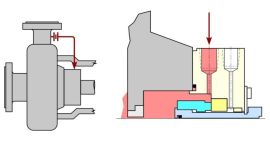
Piping plan 11[/caption]


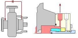
Piping plan 13[/caption]
Over many years, pump seal manufactures and end users have developed methods for modifying the local environment around the mechanical seals. They have introduced methods of improving the fluid properties of the process fluid as well as providing external fluids to enhance the sealing environment. Strategies have been developed to control, capture, monitor, and dispose of seal leakage. In addition, redundancies can be designed in to improve safety and emissions performance. The majority of the strategies and solutions have been captured in the form of mechanical seal “piping plans”.
This article contains excerpt from the paper, "Field troubleshooting common mechanical seal piping plans" by Michael Huebner and Ronald Hurst Flowserve Corporation presented at the 2017 Turbomachinery & Pump Symposia.
These piping plans define the functions, design, and operation of these solutions and allow end users to effectively apply them to the new sealing challenges. A piping plan, as any other system in the plant, must be operating correctly to achieve the desired results. This includes the initial design of the system. It also includes the proper condition and functioning of all of the components and elements in the system. Finally, it includes the availability and condition of external utilities supporting these systems. Popular piping plans are 11 and 13.
A Plan 11 is a circulation of fluid from a high pressure region of the pump, through external piping or tubing, through a flow control device (e.g. orifice), into the seal gland and seal chamber, and back into the pump. This is the most commonly used piping plan in industrial pumps.
The circulation of process fluid through the seal chamber effectively removes the seal face generated heat as well as heat created by turbulence in the seal chamber.
Common field issues
Plugged orifice – An orifice is a restriction in the Plan 11 piping which regulates the flow to the desired flow rate. The orifice can become plugged if there are particles in the process stream which are larger than the hole in the orifice. The orifice may also plug or become obstructed if there are a high percentage of solids or other debris in the process fluid.
Plugged lines (solidification, freezing) – Many pumps are operated at elevated temperatures to prevent the process fluid from becoming too viscous or solidifying. If the temperature in the Plan 11 piping becomes too low, the process may solidify or freeze and prevent circulation through the piping.
Inadequate or excessive flow – The Plan 11 flow rate is controlled by the differential pressure and the orifice size. If the orifice is improperly sized, it may result in excessive or insufficient flow rates. In multi-stage pumps, the Plan 11 for both ends of the pump may come from a common location. This requires that the piping design and orifice locations ensure equal flow to each seal.
Improper pressure differential – A Plan 11 requires a pressure differential between a high pressure region of the pump and the seal chamber. In most single stage pumps, the high pressure region will be the pump discharge. In multi-stage pump, the pressure in the discharge may be excessive and create problems with excessive flow or require complex flow control devices. This may require piping the Plan 11 from the pump crossover or an intermediate stage.
Monitoring points Temperature – on piping near the pump casing and near the seal Noise – at the orifice What to look for Since fluid should be continuously flowing through the Plan 11 piping, the temperature along the length of piping should be relatively constant. A significant difference in temperature along the pipe indicates that there is no (or very low) flow. Excessive noise occurring at or slightly downstream of the orifice may indicate an excessive flow velocity is causing cavitation at the orifice.
A Plan 13 is a circulation of fluid from the seal chamber, through external piping or tubing, through a flow control device (e.g. orifice), and into a low pressure region of the pump. This is commonly used vertical turbine style pumps.
The circulation of process fluid through the seal chamber effectively removes the seal face generated heat as well as heat created by turbulence in the seal chamber.
Common field issues Plugged orifice – An orifice is a restriction in the Plan 13 piping which regulates the flow to the desired flow rate. The orifice can become plugged if there are particles in the process stream which are larger than the hole in the orifice. The orifice may also plug or become obstructed if there are a high percentage of solids or other debris in the process fluid.
Plugged lines (solidification, freezing) – Many pumps are operated at elevated temperatures to prevent the process fluid from becoming too viscous or solidifying. If the temperature in the Plan 13 piping becomes too low, the process may solidify or freeze.
Inadequate or excessive flow – The Plan 13 flow rate is controlled by the differential pressure and the orifice size. If the orifice is improperly sized, it may result in excessive or insufficient flow rates.
Improper pressure differential – In a vertical turbine style pump, the Plan 13 flows from the high pressure seal chamber back to the pump suction or the sump. Since the seal chamber is at discharge pressure, there may be a very large pressure differential which can create problems with excessive flow or require complex flow control devices. While Plan 13’s are most often used in vertical multistage pumps, they are also sometimes used in single stage pumps. In these cases, the pressure in the seal chamber may be very close to the suction pressure in the pump resulting in low flow rates.
Monitoring points Temperature – on piping near the seal and downstream of the orifice
Noise – at the orifice: What to look for Since fluid should be continuously flowing through the Plan 13 piping, the temperature along the length of piping should be relatively constant. A significant difference in temperature along the pipe indicates that there is no (or very low) flow. Excessive noise occurring at or slightly downstream of the orifice may indicate an excessive flow velocity is causing cavitation at the orifice.


