Evolution in diaphragm manufacturing


A steam turbine diaphragm is also a very difficult component to manufacture due to the following conflicting requirements:
- it consists of three major parts made from different materials;
- it must have exceptional mechanical strength;
- it must be made with high accuracy: uniform vane heights, pitches, throats and leans.
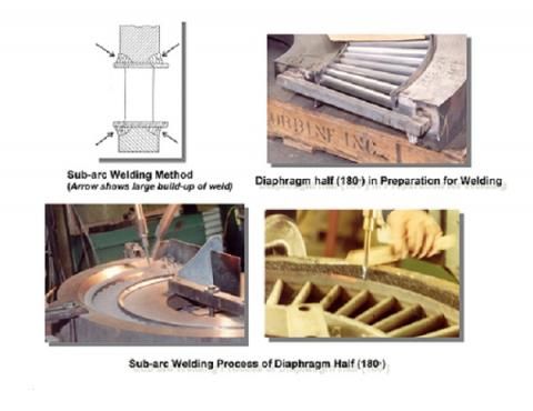
At the start of the steam turbomachinery era, diaphragms were mostly made by casting, using cast iron for the outer and inner rings and stainless steel vanes. However, these diaphragms had very low mechanical strength, temperature limits and inaccurate steam passing area. Therefore, currently their use is constrained to specific applications. Since the 1950's, sub-arc welding became the major method of diaphragm manufacturing.
A typical welded diaphragm consists of three major components: an outer ring, the "squirrel" cage and an inner ring. The "squirrel" cage is made of two concentric thin rings (called the outer and inner spacing strips) with the vanes in-between them. Each spacing strip has a plurality of through-holes matching the vane airfoil geometry. The quantity of these holes is equal to the number of vanes which are located evenly around the spacing strip circumference. Each vane is inserted through these profile holes in both spacing strips and affixed to them by welding. The completed "squirrel" cage is then welded to the inner and outer rings by four significant circumferential welds. After welding, each diaphragm must be stress-relieved and final machined.
In the beginning, the cage and the entire diaphragm were made in two 180 degree halves. The profile holes in the spacing strips were punched while the strips were in the flat condition. Only after the holes had been punched, were the spacing strips rolled to form two 180 degree semicircles of the required diameter. The profile holes and their pitching were inaccurate. The plunging process limited the spacing strip thickness to 0.140" maximum and required larger holes and radial orientation of the plunger tool axis. Therefore, the exit edge of the profile was parallel to the radial line which resulted in negative tangential lean of the vanes with all the associated deficiencies. The welding kerfs in the outer ring at the center had non-optimal geometry which could not provide the maximal possible strength. Four massive welds generated enormous heat causing significant thermal deformation. Also during welding, the thin spacing strips were often burned through, allowing melted metal to penetrate into the steam path causing damage to the vanes. Figure1 shows half of the diaphragm fabrication as described above. During diaphragm machining, the vanes in both diaphragm halves were split and partially cut at the horizontal joint. Moreover, the parts of vanes in both halves did not accurately match each other and required significant efforts (such as additional local welding and hand dressing) to form some sort of a steam passing channel in this location. Also, due to the minimal vane set-back, they were vulnerable to mechanical damage during welding and machining. Due to lack of accuracy, this method required significant hand-dressing of the entire set of vanes in order to provide the design steam passing area.


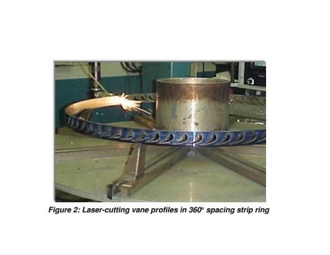
Continuous manufacturing progression in the 1970-1980's gave way to significant improvements in cage construction. The industry started laser or water-jet cutting profile holes in the spacing strips keeping them in the rolled condition (Figure 2). This allowed to substantially increase the spacing strip thickness, making them sturdier and preventing burn- through damage. Also, electronically controlled processes provided much better accuracy of the hole geometry and their pitching. Additionally, this method allows cutting the holes in such a way to provide the optimal (positive) tangential lean of the vanes with all the associated benefits. Although cage construction significantly improved, the original fabrication method of producing two separate 180 degree halves, using the original welding kerfs and sub-arc welding, remained the same with all the drawbacks associated with this method.
The next step in the evolution of diaphragm manufacturing is associated with the new machining method - Electrical Discharge Machining (EDM) which was developed in the late 1980's - early 1990's. EDM is a machining process which cuts any material with the ability to conduct electricity (regardless of its hardness) by electrical discharges. Per this process, both “participants” of machining (electrode used as a cuter and a detail to be machined) are components of an electrical circuit which also include a spark generator. The “machining area” (i.e. electrode and the part of the detail to be machined) is in a dielectric (water or mineral oil) bath which performs three major functions. It allows sparks to be created, reduces the temperature and removes residual particles from cutting. Sparks are produced by a spark generator with a high frequency (at regular intervals). A spark breakdown occurs in the point of the smallest space between the electrode and the detail machining surface. Each spark produces a temperature between 8,000 and 12,000 degree C. At such high temperatures, the material of the detail immediately melts locally, disintegrates and flushes away by dielectric, leaving a crater on the machining surface. Succession of sparks results in a succession of craters which cut through the material. EDM allows building the cage and the entire diaphragm as a single 1x360 degree plate with significantly improved welding kerfs (instead of 2x180 degree separate halves with the original kerfs). Improved welding kerfs resulted in an increase of diaphragm mechanical strength by at least 15% while thermal deformation was decreased.

Splitting the diaphragm in halves was provided by EDM wire cutting using a wire diameter of 0.010-0.015". This cutting method does not remove a large amount of metal and therefore, allows accurate mating of the split vanes at the horizontal joint. As a result, this generation of diaphragms had increased accuracy, efficiency and reliability (due to decreased stimulus) with decreased amount of hand dressing.
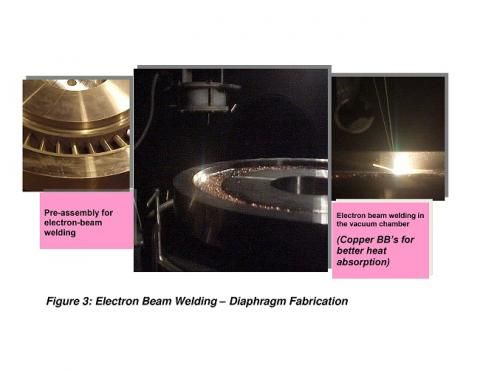
The latest step in the diaphragm manufacturing evolution is associated with the new welding method - Electron Beam Welding (EBW) which became available for civil applications in the middle of the1990's. EB welding uses a high energy electron beam in a deep vacuum, directed at the joint of tightly assembled parts. The high temperature of the beam melts the metal of both parts at the joint area, welding them together in a very short period of time, which minimizes the amount of heat. Welding in a deep vacuum produces higher quality welds which do not have any porosity or inclusions. The possible axial depth (penetration) of EB welds is significantly higher than the depth of sub-arc welds. EB welds in many diaphragms penetrate 100% of the axial vanes’ width.

This deep penetration, combined with the high quality of EB welds, as well as newer and stronger airfoils, substantially increases diaphragm strength compared to a similar diaphragm fabricated by sub-arc welding. Also, the EB welding method produces 8-10 times less heat as compared to the sub-arc method.

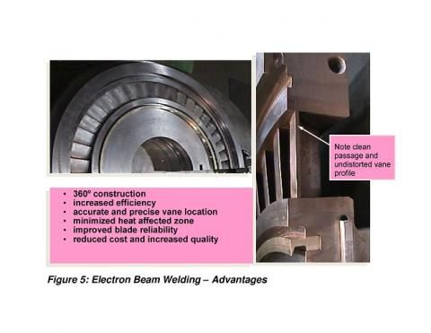
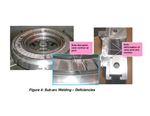
Therefore, EB welding causes insignificant thermal deformation of the diaphragm which in turn, results in higher efficiency, higher reliability (due to reduced stimulus on the rotating blades) and minimizes the amount of hand dressing. Figure 3 shows major steps in diaphragm EB welding while Figures 4 and 5 display the differences in diaphragm quality produced by sub-arc and EB welding.
Previous Articles
Progress in mechanical strength calculation
Optimal edge-to-edge clearance in blades
Contoured end wall in HP nozzle rings and diaphragms
Optimal tangential lean of vanes
Past and current steam turbine airfoils


