Avoiding process loop contamination through seal amplifier systems
Seal gas on centrifugal compressor shaft-end seals is deployed for applications ranging from
localized warming of the contaminated drain area of oil seals in refrigeration service to protection of close clearance sealing faces of dry gas seals.
In all applications, over 90% of the seal gas entering the gas side labyrinth enters the process loop. This leads to pressurization of the loop during settleout conditions, and contamination of closed loop systems such as the refrigeration and hydrogen recycle loops often used for liquefying natural gas, production of polyethylene/polypropylene, and refinery applications.
This article addresses the proper selection and control of seal gas to avoid process loop pressurization and contamination through ingestion of a gas not compatible with the closed loop process gas.
Both misapplications lead to the requirement to flare the loops prior to returning to full on specification production following an unscheduled plant trip or restart after a scheduled maintenance period.
Flaring of the process loop to reduce the settleout pressure may be required if the compressor drive system is incapable of achieving a full pressure restart. Flaring of the process loop after restart may be required to bleed off design loop gas that has been contaminated by an incompatible external seal gas supply and replenish the loop with 100% pure refrigerant to achieve design end product. A typical example is a propane refrigerant loop that utilized fuel gas as an external seal gas supply during settleout condition awaiting restart.
Both incidents not only lead to additional flaring, which has an immediate detrimental effect on the Plant’s “Blue Sky” initiative, but also delays the return of the plant to full production often 12-24 hours, not to mention the cost to replenish the contaminated loop.
This significant loss in revenue can easily justify the Project’s Rotating Equipment Engineer to deploy as simple system to eliminate these operational shortfalls.
The Paper
As a site rotating equipment commissioning engineer your first encounter with the compressor seal gas is during the process loop leak checks during construction. Here your team is systematically pressurizing the loops with often nitrogen to minimize further rust formation of loop components, as well as evacuate the system of air in preparation for the introduction of hydrocarbons. The goal of the team is to pressurize the loop to a fixed pressure and hold, while monitoring the pressure level for leaks to validate system tightness. If a leak is encountered, the loop is depressurized, the leak remediated and the process repeated. This is a critical step, as a false reading can result in a long term undetected leak that after introduction of hydrocarbons can leak to a problem especially if the leak occurs in an area not covered by gas detectors.
As the team moves to the centrifugal compressor loop, the team must be aware of prerequisites required prior to performing the pressure test as well as critical loop venting procedures to avoid damage to the compressor bearings.
So here is a good place to hold while the site rotating equipment commissioning engineer assures the commissioning team is properly briefed on the hazards that are present.
Warning
First, and foremost, is that high concentration of nitrogen will lead to death when inhaled in a closed space. We must assure we never again have to pull a deceased fellow worker and his friend from a nitrogen rich atmosphere, often because they were not aware of the extreme danger. I have a personal encounter just leaning into an open pipe to inspect cleanliness, acknowledging that it only takes one breath of 100% nitrogen before you begin to lose control. The commissioning team must assure all members are properly trained and that proper respiratory protection is deployed when entering loops.
The second area of concern is the venting of the loops after completion of the loop checks. The potential energy stored in these large loops is significant and can lead to extremely high motive gas forces when loops are evacuated at high uncontrolled rates.
We have seen uncontrolled venting exceed the breakaway torque required to break loose and spin a motor/gear/centrifugal compressor string even without lube oil supplied to the bearings. The result was disastrous, as shown below.
The location of the vent and vent rate is critical. The team should avoid selecting a vent location that would allow reverse rotation of the unit, even if the oil system was activated. This is because certain bearing designs incorporate leading edge groove technology as shown in the above thrust bearing that will not develop the proper oil film in the reverse direction. Additionally, certain dry gas seal technologies utilize sealing face lift technology that will only operate in the forward direction.
So again, it is the responsibility of the site rotating equipment engineer to assure the commissioning team is properly trained and that a detailed procedure is developed when pressure testing process loops that include centrifugal compressors. The following is a typical process loop.
As the majority of new applications utilize dry gas seals, commissioning of the seal gas is one of the key prerequisites for the commissioning team to perform to avoid damage to the dry gas seal faces. The following is an example of a dry gas seal support system.
So a quick prerequisite check list for loop testing would be:
- Commission the tertiary seal, separation gas to avoid oil ingestion into the secondary seal face.
- Commission the lube system to protect the rotating equipment from damage in the event of an error during loop depressurization.
- Commission the primary seal gas to protect the gas seal faces.
- Now back to the paper…the prerequisites have now all been satisfied and the compressor is ready for loop pressure testing. The rotating equipment engineer must find an external seal gas source, typically nitrogen capable of maintaining the design seal gas to reference gas delta p, typically 5 psid above the process loop test pressure, typically 5 psig. This put the source pressure minimum at 10 psig plus losses across the seal gas system valves and filters.
- Caution
The external source maximum pressure must be limited to avoid lifting of the relief valves in the suction separator. As typical nitrogen supply is 100 psig, care must be taken to regulate this pressure down to the 15-20 psig level.
Once design buffer gas differential is achieved, the commissioning team will pressurize the loop to say 5 psig and monitor it for leaks. Once they determine the system is tight, the actual tightness test, typically 1 hour is conducted. Depending on size of the loop, compressor gas side labyrinth clearance, and length of the test, the team may notice an actual increase in loop pressure. In one extreme case we left a leak test set up overnight. When we arrived the next morning, we were advised that the suction separator relief valves had lifted.
More importantly, it is difficult for the commissioning team to conclude that the loop is pressure tight since the seal gas is constantly being bled back into the system from and external source. As discussed earlier, this compromises the results of the loop test and could lead to further hazards once hydrocarbons are introduced.
One action the commissioning team can take is to limit the source pressure of the seal gas as explained above. However, in a similar unmanned extended test, the design seal gas differential will gradually deteriorate leaving the dry gas seal faces vulnerable to foreign material damage as the primary seal continues to leak and in certain cases, the rotor can actually shift rapidly axially during loop depressurization resulting in momentary step increases in primary seal gas leakage.
What we need is a device that:
· Maintains seal gas differential during these commissioning loop pressurization tests, improving the validity of the tests.
· Maintains settleout pressures at their initial level eliminating the need to vent the loops to flare prior to restart due to driver limitations.
· Maintains settleout pressures at their initial level avoid potential lifting of the suction separator relief valves
What we also need is a device that maintains design seal gas differential pressure, without the introduction of a gas incompatible with the process loop gas that can have the following negative effects:
·Inadequate loop cooling due to off design process gas
·Spurious trips during restart or bogdown trips during recycle valve opening due to increased compressor horsepower as a result of off design process gas.
The following illustrates the results of an LNG MR loop operating with a higher than design MW gas. As shown, the compressor discharge pressure was significantly higher than predicted.
A series of flaring and replenishment of loop process gas was required to restore gas properties to their design levels, allowing the plant to produce on spec. LNG.
The solution to these problems is a device that takes its supply from the process loop then slightly raises it to the required seal gas differential pressure.
Using PV = nRT, the increase in pressure in the loop when the suction is fed from the loop, is only a function of the temperature rise. T
he loop pressure will continue to increase to the external source pressure if left intact long enough. When the supply to the amplifier is connected to the loop the loop remains at the settleout conditions, while not introducing incompatible seal gas into the loop. So a simple seal gas booster system, commercially know as an Amplifier System, is a readily available product that solves all the above problems.
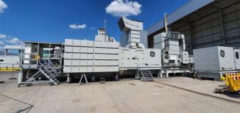
Amplifers were first developed for remote pipeline compressors soon after the development of dry gas seals, where a higher than pipeline pressure source was unavailable when the compressor was at settleout conditions.
They were recently deployed on the Qatargas 2 project process loops, to reduce plant flaring and increase plant availability by supporting the pressurized restart initiative and allowing the plant to achieve design LNG quality much sooner after restart. The amplifiers eliminated the need to vent and replenish contaminated refrigeration loops as fuel gas is often used for the seal gas during settleout conditions.
Due to the 350mm seal size, dry rotary screw compressors with variable speed drives were deployed.
Deployment of Amplifiers should consider the following operating modes:
- System shall be capable of operation on both nitrogen and process gas. As illustrated in the video the latest drive technology allows for a step change in pump operating speed allowing the amplifier to supply the required flow to clear the start permissive on different gases.
- System logic should start the amplifier if the main compressor trips and stop the system during restart as the compressor reaches minimum governor.
- Deployment should utilize a redundant pumping mechanism to support the plant RAM targets.
- After initial commissioning, if nitrogen is permanently connected to the dry gas seal system, the Plant should swing the spectacle blind on the nitrogen supply to avoid backfeeding hydrocarbons into the nitrogen system.
- So, here’s a simple device that can be easily justified during project FEED as well as on existing plants. We have shown in this paper the following effects of deploying amplifier systems on closed loop processes:
· Plant Construction – Safer more reliable loop pressure tests
· Plant Availability – Faster restart as flaring to reduce settleout pressure is eliminated
· Plant Production – Shorter restart as flaring to correct loop gas quality is eliminated
· Operating Cost - Elimination of replenishment of contaminated loop process gas
The elimination of plant flaring and the associated costs of unscheduled flaring can easily justify the costs of deploying this system. In conclusion we have presented the deployment of a small, relatively low cost system that can have an enormous effect on our “Blue Sky” initiative.
The next article addresses a second “Blue Sky” initiative, full pressure restart.
(The author is Rotating Equipment Consultant, Jordan Cove LNG.)
Newsletter
Power your knowledge with the latest in turbine technology, engineering advances, and energy solutions—subscribe to Turbomachinery International today.


