
|Articles|April 25, 2016
Role of gear units in high-speed turbomachinery
Author(s)Amin Almasi
Advertisement
Gear units play a critical role in high-speed turbomachines, especially in speed match. Practical notes on high-speed gear units are discussed here:
Turbomachinery gear unit failures are caused because of gear tooth surface pitting modes, various wear types, and sudden breakage of different modes of gear. The gear wear could be continued for a long period of time if the wear rate is low.
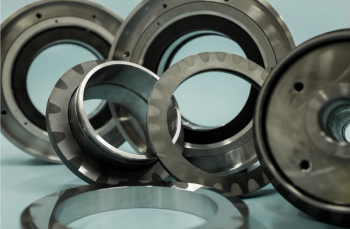
(A gear unit. Photo: Global Energy Technologies Ltd.)
Progressive pitting can result in high vibration, high mechanical and thermal loading, and eventually destroy the gear sets. The wear and pitting need time to reach a certain level that can result in a catastrophic failure. This can be detected using a proper condition monitoring method. However, a sudden breakage due to bending loads can result in a failure, without any warning.
To eliminate unexpected gear failure to the maximum extent possible, commonly-used specifications mandate a sufficient margin for gear tooth bending while designing. Considering the wear, the lubrication selection (particularly correct viscosity grade, sufficient flow and other lubrication parameters) plays an important role. It could be difficult to provide an optimum margin for the pitting. Increasing the gear size or gear hardness is the main tool for a better margin on the pitting. Both could cause other problems and a sharp increase in the cost.
There are two concepts with regard to hardness design (related to the material and heat treatment) as far as gear units used in high-speed turbomachine applications are concerned:
Medium-range hardness gears: Medium-range hardness gears are not sensitive to operational errors and wear before the gear failure. The noise levels on medium-range hardness gears increase with wear. This noise could be used as an indication for wear and possible failure.
Very hard gears: These gear units are used in some compact, high-speed turbomachines with high power density. Very hard gears are more susceptible to scuffing because of high load intensity and sliding velocity.
The helix angle is selected for best results -- optimum performance, minimum overlap ratio and superior load sharing. The axial load, is another function of the helix angle, and is recommended for single-helical gears, which result in a relatively lower angle in the single-helical gear unit design. As a rule of the thumb:
The single-helical helix angle: between 5o to 22o .
The double-helical angle: between 18o to 45o .
Gear Unit Lubrication and Casing Design
In gear units, the gear teeth can be subjected to very high contact pressures because the metal-to-metal contact depends on the lubrication. This high pressure could reach extremely high levels due to operation errors, misalignment, different degradations and loss of lubrication properties of the oil. Less than 30 percent of the oil used for high-speed gear units is used for lubrication. Around 70 percent (or sometimes more) is employed for cooling.
Heavy lubricants (say above VG 100) are commonly used for gear units working at high-speeds and high loads. A proper casing design is key for gear unit reliability and performance. An optimum clearance should be ensured around the gears (and between the gears and casing) to avoid oil choking. Moreover, a correct thermal design is also important. Uniform temperature patterns should be maintained for gears and casing, and the thermal distortions also should be limited.
The gear housing and the mounting type/supports of gear unit are important considerations for performance and reliability. The gear unit casing should also be sufficiently rigid to ensure low deflections under load so that proper alignment can be maintained.
Generally, the same oil (as the job oil) should be used for the flushing at the pre-commissioning stage. The oil is drained and fresh oil is used for the commissioning, the start-up and the first day of operation. Again, the oil is drained (after 24-hours operation under load) and fresh oil is filled for the first six months of the operation. Oil analysis is the best way to identify an optimum oil change interval, which is usually between 6 months to 2 years.
Gear Unit in Turbomachinery
It is important to consider the effects of all machinery in a train on gear unit. It is true that some gear units fail due to external equipment effects on the gear unit. Usually, the gear unit manufacturer is less informed about the turbomachine train where the gear unit will be installed. A common lubrication system for the turbomachine and the gear unit could be a reason for failure since the selected common oil for a train is nearly always a compromised option, and is usually a poor lubricant for the gear unit.
The mounting and testing (including alignment and adjustment) of a gear unit into a turbomachine train is a precision job. It has a great effect on train operation and reliability. A poor alignment can cause unequal distribution of gear tooth loads and distortion of the gears. An expensive gear unit can be destroyed within half a day's operation, if improperly installed. Before the start-up, the gear face contact should be checked for accuracy. Usually, 90 percent gear face contact should be achieved.
Some high-speed, high-load gear units (particular those with very hard gears) are produced with helix angle modifications considering the bending and torsional deflections (due to high loads of these gear units). For these special gear units, less than 90 percent gear face contact could be acceptable. The alignment of high speed gear units should be checked at operating conditions (known as “hot alignment check”).
Amin Almasi is a Chartered Professional Engineer in Australia, Queensland and U.K. (M.Sc. and B.Sc. in mechanical engineering). He is a senior consultant specializing in rotating equipment, condition monitoring and reliability.
Advertisement
Related Content
Advertisement


Advertisement
Advertisement