The hermetically sealed compressor for offshore and subsea
The state-of-the-art compressor for offshore and subsea compression is hermetically sealed direct driven centrifugal unit using magnetic bearing without seal or oil auxiliary systems. This is a simple and small footprint machine with maintenance intervals more than five years.
The offshore applications present four major challenges to rotating machines: 1- Requirements for light weight and compact design. 2- High expected reliability and availability. 3- High level of safety and hazardous area classifications. 4- Offshore harsh environmental conditions (corrosion, dynamic loadings, etc).
A growing number of compressors are being used on offshore applications such as offshore platforms and floating production storage and offloading (FPSO) vessels. Repair and downtime costs have been estimated several times higher in offshore applications compare to land based applications. One reason is significant travel and logistic requirements. Classic offshore centrifugal compressors (usually gas turbine driven) have to deal with many issues and challenges such as low reliability of gas turbine drivers, high maintenance of oil and seal systems, etc. Many existing offshore centrifugal compressor train designs cannot satisfy modern offshore project expectations.
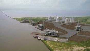
Looking to the future, an important remote location for compressors is the ocean floor. It is generally acknowledged that gas production rates increase when compression occurs close to the wellhead. When machines that typically operate on top-of-sea platforms are on the ocean floor, the need for some platforms is eliminated. Eliminating platforms is, in itself, a huge economic incentive to the development of subsea capabilities. Currently, subsea pump technology is more mature than subsea centrifugal compressor technology. This is because pumps typically operate at lower speeds than compressors. Production companies are putting pumps on the ocean floor today. Subsea centrifugal compressor development is not mature yet and it is not common-in-use. In fact, the cost of installing a gas compression system on the seabed is enormous, and economic benefits can be achieved only if the reliability of these systems can ensure an uninterrupted service for a period of time that has been quantified as five years or more.
Conventional compressors are difficult to use for new offshore applications. The use of a conventional compressor is out of the question for subsea installation. Solution is hermetically sealed direct motor driven compressor unit. Several vendors manufactured hermetically sealed compressors, and some of them have proven their reliability in various applications. This article reviews hermetically sealed direct coupled motor-compressor technology for subsea and offshore applications.
The gas turbine was widely used in classic offshore installations because of its superior power to weight ratio over other drivers. It was quite popular for use in offshore remote locations where the package concepts minimize the need for support equipment. Gas turbine usually needs gear unit to match speed and always has demonstrated relatively high maintenance. Because fuel can be more efficiently and reliably converted to electricity in large central power units (with 100% spare) variable speed electrical motors (specifically in variable speed direct coupled hermetically sealed configuration) become such that began to displace the more convenient gas turbines in offshore applications. This arrangement receives a high degree of attention because of more efficiency and higher reliability.
Integrated compressor design
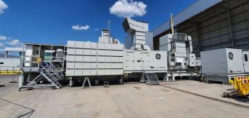
Compact and modern offshore and subsea compressors feature a barrel type casing bolted to the variable high-speed electric motor casing in such a way as to form a sealed package. There is an alternative design which two barrel compressors are coupled, on each side of the centrally locate motor. The active magnetic bearings generally are supporting both the compressor and the motor shafts. The use of magnetic bearings allows the machine to run in dry conditions, eliminating the lube oil system entirely. The hermetically sealed package also allows elimination of the shaft end seals of the compressor. Altogether, this modern design simplifies installation and reduces the footprint 50 to 60% when compared to a conventional compressor.
Usually hermetically sealed direct driven centrifugal compressor designs are available in standard ratings. For example one manufacturer offers two different ratings, first model discharge pressure around 70-90 bar used for standard offshore gas applications and second model for pressures of 170-190 bar, for conventional gas re-injection services.
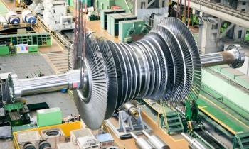
The impellers are usually arranged in a back-to-back configuration inside the compressor casing (inline arrangement is rarely used). The back-to-back arrangement allows the machine to operate with the two impeller groups in series or in parallel. The first impeller is designed to carry a slightly larger flow than all the others because a portion of the first stage of compressed gas is extracted and used to cool the motor and the bearings and then is returned to suction. The amount of cooling gas recycled depends on its composition, temperature and pressure, and can be between 5 and 10% of the volume handled by the machine. Impeller number can vary from a minimum of two to a maximum of eight according to the compression ratio required by the service (generally closed type impeller used, each has pressure ratio around 2). For offshore and subsea applications impellers nominal diameter in the range from 300 to 600 mm is in common production range.
The motor section is usually developed by other manufacturer and close cooperation is always required between compressor manufacturer and motor vendor. In majority of cases, motor and compressor are connected through a conventional metallic flexible coupling (a reliable high torsional stiffness coupling with ample service factor). The flexible connection of the two shafts allows for maximum freedom in the design of the two machines which, in practice, is the same as in a conventional compressor and motor assembly. Alternative is common shaft for both the motor and the compressor. This is offered configuration of vendors that can produce both compressor and advanced motor.
The compressor bearing span depends on the number of impellers assembled on the shaft. For inspection and maintenance, the motor and the compressor have access through the respective end covers of the barrel-shaped casing. The axial thrust of the compressor is absorbed by the balancing drum or back-to-back design. Axial magnetic bearing placed at one end of machine to absorb the motor and compressor residual axial thrusts. Variable high-speed induction motors are used in common application range of 3 to 30 MW. For example one manufacturer has two versions of hermetically sealed direct driven centrifugal compressor and offers four different frame sizes including 7.5, 10, 15 and 20 MW. Another vendor developed the line of hermetically sealed compressors features 4, 10, 20 and 30 MW classes. The motor nominal speed varies according to the size. As an indication, speeds around 20,000 rpm are available for motors in the lower part of the power range (usually below 10 MW) while speed around 10,000 rpm are possible for above 10 MW units. These motors usually can be operated between 40 and 105% of nominal speed. The main advantage of hermetically sealed design is in the footprint savings. Efficiency wise, the small advantages are gained. This concept is also environmentally friendly as it operates with no emissions and with very low noise, which are main today concerns.
Some vendors use vertical hermetically sealed machine with the driving motor placed over the multistage compressor (variable speed electric motor in the upper section and the compressor located below). These vertically arranged hermetically sealed compressors reduce the footprint compared to a horizontal compressor package. They generally feature a common shaft for both the motor and the compressor.
Untreated gas
Hermetically sealed machines use, as a motor-cooling medium, the same gas that is partially extracted after the first compression stage and then returned to the compressor inlet. This practice has proven safe when handling clean gas. Nearly all hermetically sealed motor-compressor units in operation today are handling treated (clean) gas. For upstream applications, compressing gas at the wellheads, natural gas is not a clean gas. It carries over sand, water and sometimes H2S (sour gas) and other corrosive components. The gas composition can also change over time and the machine should be able to cope with such changes. Compression of dirty gas with high reliability to guarantee a minimum of five year uninterrupted operation is required for many subsea compressions. Untreated gas can create deposits on the hot spots of the motor and bearing stator windings with the inherent risk of short circuit and failure of motor and magnetic bearings. Current solution for untreated gas subsea compression applications is motor with a solid, non-laminated rotor of NACE compliance (copper components eliminated) using symmetrical cooling system design (external coolers not feasible). Also the canned type magnetic bearing for motor and compressor.
Case studies
The first case study is horizontal hermetically sealed subsea centrifugal compressor for natural gas (molecular weight of 18), weight flow of around 90,000 kg/h, the suction pressure around 50 barg, the discharge pressure around 150 barg and consumption around 5.5 MW. Driver is variable speed motor up to a maximum continuous of 12,000 rpm. Operation with treated gas was totally satisfactory.
Second case study is vertical hermetically sealed compressor, with common shaft, featuring a 6.3 MW variable speed induction motor running at 12,200 rpm, with an operating speed ranging from 30 to 105% of nominal speed.
These two compressors are for clean and dry natural gas applications and demonstrate acceptable performance. Based on current technology it is possible to install subsea compressor for clean gas applications with whole compressor module maintenance intervals of not less than five years. But extensive research and test programs are currently performing to apply this technology for upstream untreated gas which include considerable amount of water, corrosive agents, etc.
Conclusion
The hermetically sealed casing and the use of magnetic bearings allow for the elimination of shaft end gas seals and lube oil systems, two components that need periodic maintenance. Also these machines are less than half the size (and weight) of traditional compressors. More vendors are invested in horizontal configuration of hermitically seal compressor. Vertical design offers less foot-print. Common shaft for both the motor and the compressor are preferred which is possible when manufacturer has sufficient capability for both compressor and motor. Motor section is usually standard. Compressor part is tailored to the application in the size and number of impellers, taking into account the characteristics of the gas to be handled can vary substantially in time.
(Amin Almasi is a rotating machine consultant in Brisbane, Australia)
Newsletter
Power your knowledge with the latest in turbine technology, engineering advances, and energy solutions—subscribe to Turbomachinery International today.


