Thermal analysis for energy savings
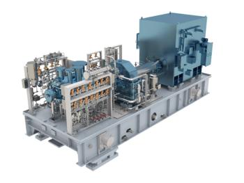
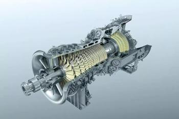
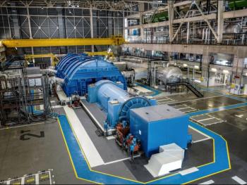
One of the most important factors that should be considered in the design (and operation) of any turbomachinery is the thermal structure (or the thermal arrangement). Appropriate materials, cooling systems and insulations (or thermal shields) should be selected for turbomachinery based on a proper thermal analysis.
Over the past decade, thermal analysis has started to receive more attention. In fact, with the increasing requirements for compactness, energy efficiency, cost reduction, lightweight design, extreme temperatures and the need to fully exploit new topologies and materials, it is necessary to analyze the machine thermal circuit to the same extent as the other aspects such as the fluid-dynamic. With a thorough understanding of thermal arrangement, designers can take steps to optimize the thermal structure such as to minimize the temperature differences between the machine casing and the environment (or any heat sink) for more efficient and more reliable operation.
For most turbomachinery, accurate temperature distribution is critical for operational and safety reasons; to control the peak temperature for hazardous locations, to predict the fatigue under the heating-up and cooling-down processes, and to calculate the number of consecutive starts. Dimensional changes can occur due to temperature deformations at the machinery elements.
The thermal study plays a crucial role for any gas turbine or steam turbine. A large portion of generated heat in a turbo-compressor is rejected by the intercooler, the after-cooler and the lubrication oil system. Proper design of these components requires thermal data of the compressor. A typical electric motor having an assumed efficiency of around 94-98% dissipates 2-6% of totally energy as the heat. The main portion of this heat is absorbed by the electric machine cooling systems; heat is also rejected from the casing to the surrounding environment.
There are two main approaches to machinery thermal calculations: analytic lumped circuit model and numerical analysis. The lumped-parameter thermal network method can successfully be used for thermal analysis of nearly all types of turbomachinery. In this method, the solid components and the fluid are lumped into fair number of nodes (typically 100-400 nodes). Grouped parameters are calculated from size-related information, the thermal characteristics of the materials and various heat transfer coefficients. Detailed features are combined into a model with averaged properties. The temperature at every node in the thermal model can be calculated by solving energy balances. It is necessary to account properly for the radial heat transfer, heat generation distribution, heat radiation, contact conductance and surface convection modeling. Convection heat transfer usually plays an important role in a turbomachinery thermal analysis. The forced convection heat transfer due to the rotor rotation (and also the convection around the machine ends) should be properly modeled. Today thermal analysis software has been developed for turbomachinery. The user inputs geometric data for the machine under consideration using the radial and cross-sectional graphical editors.
Entropy balances (based on “Second Thermodynamic Law”) allow for a calculation of the entropy generation or, equivalently, the energy destruction in a turbomachinery. Evaluation of the energy destruction in a turbomachinery allows for an identification of the mechanisms that contribute most to the overall irreversibility and destruction of the useful work. This analysis can identify the areas in a turbomachinery where potential thermal performance improvements can be done.
Generally, high temperature differences between components and fluids (main stream fluid, cooling water system, lubrication oil stream, surrounding environment, etc) can result in the energy destruction. For example, turbomachinery arrangements that result in high temperatures at bearing systems can cause high temperature difference between the lubrication oil and the surfaces in contact with the oil. A considerable amount of heat can be transferred to the lubrication oil which can cause the lubricant problems, the heat waste, the requirements for very expensive lubrication oil systems, large lubricant pumps, expensive oil coolers, or special lubricant requirements. The same is true for cooling systems. As noted, considerable amount of energy is also destroyed near the outer housing (or the casing).
Practical experience shows the real thermal structure and the temperature distribution (and associated stress, deformation, strain, etc) in the turbomachinery units usually remain inadequately studied. It negatively affects the design, the performance and the reliability. An accurate evaluation of turbomachinery thermal characteristics right at the design stage is generally required.
Author: Amin Almasi is a registered professional engineer in Australia and Queensland (M.Sc. and B.Sc. in mechanical engineering). He is a consultant specializing in rotating equipment, condition monitoring and reliability.
Newsletter
Power your knowledge with the latest in turbine technology, engineering advances, and energy solutions—subscribe to Turbomachinery International today.


