When rotary pumps can replace centrifugals
Within the U.S., and probably worldwide, piping systems, pipelines and the pump trains that provide the flow within these systems have seen fluids with ever increasing specific gravity and viscosity. Pipelines systems were in the past designed for flow of 5000 BPH to 20,000 BPH on crude oil of 20 cSt to 50 cSt. However, these pipeline systems found operating flows declining by the last decade of the last century and in many cases conditions in the early 2000’s found flow at 10% to 20% of the original and viscosity100 to 200 times higher.
This article contains excerpts from the paper, “Conversion from Centrifugal to Rotary Positive Displacement Pumps” by M M Bruck of Hydraulic, Measurement, and Inspection Consulting, LLC at the 2018 Asia Turbomachinery & Pump symposium.
Kirby pump station had two pumps. Pump 2 was 4x6x10 centrifugal pump with four stages and a BEP of about 1570 BPH and Pump #1 which was a 6x10x19 2 stage double suction first stage centrifugal with a BEP of about 3500 BPH. Pump #1 had issues of MAOP for the desired flow rate and Pump #2 had a horsepower issue for the desired flow rate.
Operating costs increased but not sufficiently to financially justify the replacement of the centrifugal pumps with rotary PD pumps purely from operational savings. Also, the common belief was that it’s not possible to run PD pumps in series on a pipeline.
Some experienced engineers convinced a few others and one brave systems programmer to try to model the proposed operation with rotary PD pumps in series. The model showed that the system was stable when ASD’s (aka VFD’s), flow recirculation, and pressure relief valves at downstream stations were properly applied. One supplier replied to a request for users who possibly had systems similar to the one that was modeled and that began the task of redesigning the pipeline station and operation.
Pipeline pumps were rated for 3500 to 7000 BPH on 20 cSt crude (original design)
Because of viscosity correction the centrifugal pump efficiency varied from about 10-20% when MTBR allowed the pumps installed to run. Further, pressure management on the pipeline system was not evenly distributed between the stations. The application seemed ideal for a rotary positive displacement (PD) pump.
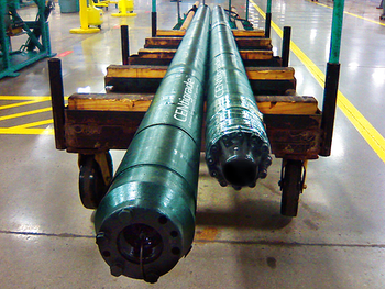
Pipeline personnel worked with vendors to select a probable pump. After observing first-hand the operation of a pipeline system in Canada, the pipeline company then used computer simulations to model the hydraulic responses of the pump, controls and pipeline system.
Additional items that were addressed as part of the re-design of the station were: Equipment vibration level reduction as well as flow-rate flexibility and control system upgrades for the system and re-designed station.
The following could be not be changed:
• MAOP could not change from 1150 psi (825 to 875 psi discharge at average flow)
• Flow rate range had to remain 400BPH to 800BPH (typical 700 BPH)
• Viscosity range was 1500 to 3000 cSt
• The local power supplier would not allow more than 400 HP motors with across the line starting because of inrush current possibly causing “flicker” or voltage dip during pump/motor start-up
It was necessary to determine if the pipeline controls could react properly with the proposed rotary PD pumps. Therefore, a hydraulic simulator was programmed with two rotary PD pumps that were controlled by ASD’s and that controlled the station discharge pressure, pump suction pressure, pump horsepower, pipeline flow transite rate.
It was assumed that normally the controller would control on the pump suction parameter. However, there was concern that an upset requiring a rapid control shift from pump suction to some other parameter – probably station discharge pressure but possibly horsepower could occur. The primary concern with these parameters was that one would “fight” another and the pump control system at the station would go out of control and overpressure the station piping or downstream pipeline. There was also concern that if an immediate stop was issued to the pump controls the bypass and relief piping could not respond rapidly enough to prevent overpressure of station piping. These were all addressed.
The system has been operating for nearly 10 years at ~45% higher throughput with ~10% additional power cost. This a net of ~35% flow increase for the same power cost.The main reason that the power cost is not lower is due to electric company demand charges. The new pumps are so reliable that they run nearly continuously. Maintenance costs have declined to approximately zero.When crack spread, maintenance cost, and power costs are summed, it is estimated that the installation paid for itself in about 2 years.
Newsletter
Power your knowledge with the latest in turbine technology, engineering advances, and energy solutions—subscribe to Turbomachinery International today.


