What are magnetic drive sealless pumps
A magnetic-drive, sealless, centrifugal pump offers complete containment of process liquid, utilizing product lubricated bearings within a pressure boundary and a magnetic coupling to transmit torque across a containment shell.
This article contains extracts from the paper, "The application of ultrasonic technology to improve the reliability of magnetic drive centrifugal pumps" by Samuel Tomlinson and David Clarke of Sundyne HMD Kontro Sealless Pumps and Andrew Hunter of Tribosonics Ltd.


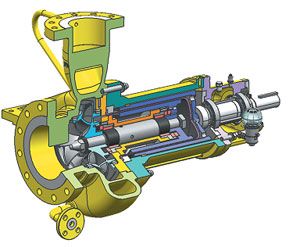
A pump casing consists of the suction and discharge flanges and the casing volute which houses the impeller. Rotation of the impeller imparts energy to the liquid causing the pump to operate. The impeller is supported by the internal pump shaft and shaft sleeves. The shaft is supported by the bush holder consisting of a rigid holder and bushes or bearings which run against the shaft sleeves. Completing the inner rotor assembly is the inner magnetic ring. This is a ring of co-axially arranged outward facing permanent magnets, which are fully encapsulated with a resistant metallic sheathing.
The final component of the liquid contact assembly is the containment shell. This component is statically sealed with a gasket against the casing. The containment shell is usually manufactured from a high strength, non-magnetic, corrosion resistant alloy.
Outside of the primary pressure boundary is a second, outer magnetic ring, with magnets that face inwards. The outer magnetic ring is located in the coupling housing which is connected to the external bearing assembly. When the pump is filled or ‘primed’, the liquid is completely contained without the use of any dynamic seals.
The principle of operation is very simple. The magnets in the outer and inner magnet rings are attracted to each other, so as the electric motor rotates, the outer ring and the inner ring rotate at the same speed, thus rotating the impeller and causing liquid to be pumped. The containment shell is located between the two attracting magnetic rings, and will be subjected to the rotating magnetic circuits as the outer and inner magnetic rings rotate.
For strength and temperature resistance, the containment shell is usually manufactured in a metallic material which is electrically conductive. It is this property in conjunction with the rotating magnetic circuits that causes eddy currents to be induced in the containment shell. These induction losses manifest themselves as heat and have to be accounted for when applying the pump.
A small portion of the pumped liquid is also used to cool the magnetic coupling and lubricate the internal bearings. The pump uses the pressure generated by the impeller to feed a small amount of pumped product into the rear of the pump. Here the flow splits and a small portion of the flow lubricates the internal plain bearings and returns to the pump casing volute.
The majority of the flow enters the holes in the pump shaft and travels to the rear of the containment shell where it splits radially and flows along the annulus between inner magnetic ring and the containment shell tube. As already mentioned the metallic containment shell has associated losses, which need to be cooled, and it is this internal flow that provides this cooling.
After the flow has travelled over the inner magnetic ring, it then returns to the bulk flow in the casing volute through the return feed hole behind the rear of the impeller. It is important to understand the impact of circulating the pumped liquid in the internal feed system.
As the liquid is circulated, its pressure drops and temperature increases, and for safe and reliable operation, the liquid needs to remain stable at all times. It has often been suggested that monitoring the condition of the internal flow would be of great assistance to the user of magnetic drive pumps, in particular with regards to vapour content.
However, the technicality of implementing such a system has proven to be particularly challenging. The pump construction prevents easy access to the process liquid that is circulated in the rear of the pump, as the pressure boundary (containment shell), is surrounded by the rotating outer magnet ring. Furthermore, if this boundary was breached to gain access to the liquid, it would effectively lose its sealless characteristic, thus non-invasive techniques would be preferred.
Newsletter
Power your knowledge with the latest in turbine technology, engineering advances, and energy solutions—subscribe to Turbomachinery International today.


