COMBINED CYCLE TECHNOLOGY TRENDS
A REVISED OUTLOOK ON THE FUTURE PROSPECTS
FOR GAS TURBINE DEVELOPMENT AND EFFICIENCY
BY S. C. GÜLEN


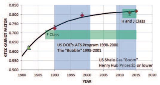
Figure 1: Historical improvements in GT technology.
In an earlier article published in Turbomachinery International 2016 Handbook (P. 24), the author provided a brief glimpse at future prospects for gas turbine (GT) combined cycle technology based on its historical evolution (Figure 1). Since then, major OEMs have announced “world records” and published performance ratings as high as 64% (net
lower heating value at ISO base load). However, there are thermodynamic limits imposed on GT simple and combined cycle performance.
Where can further efficiency improvements be realized? In many areas of gas turbine technology, only nominal advances are possible. The most promising developments for further gains in efficiency are probably to be found in the hot gas path and the axial compressor. However, the gains anticipated in these and other areas of technological upgrade are not expected to boost efficiency by a large margin.


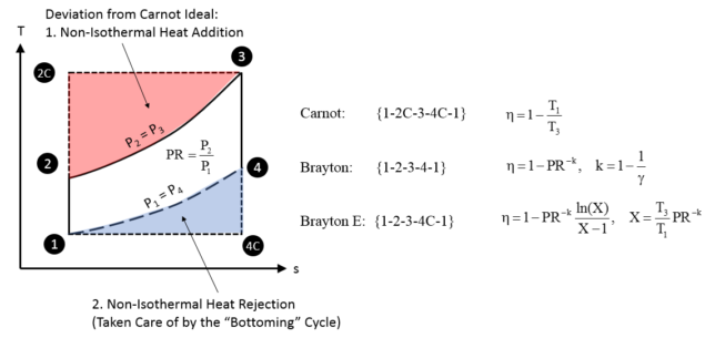
Figure 2: Gas turbine cycle hierarchy (Brayton E is the Enhanced Brayton cycle, which is the ideal proxy for the combined cycle)
Thermodynamic limitations
The GT is an internal combustion engine. As such, it is a member of the larger family of heat engines. The starting point of any heat engine is the thermodynamic cycle that describes its basic operation. For the GT, it is the Brayton cycle.
Like all heat engine cycles, the Brayton cycle is a poor approximation of the thermodynamic ideal quantified by the hypothetical Carnot cycle. The cycle hierarchy is illustrated graphically on the temperature-entropy (T-s) diagram (Figure 2).
- Carnot cycle is the theoretical maximum imposed by heat source and sink temperatures, T3 and T1, respectively
- Next comes the air-standard, ideal Brayton cycle, whose performance is controlled solely by the cycle pressure ratio, PR
- At the bottom lies the real cycle beset by hardware imperfections, which, strictly speaking, cannot be depicted on a T-s diagram.
The deviation of the ideal, air-standard Brayton cycle from the Carnot cycle can be quantified by the two, roughly triangular areas in the T-s diagram of Figure 2: heat addition imperfection quantified by the area {2-2C-3-2}; and heat rejection imperfection quantified by the area {1-4-4C-1}.
The second imperfection can be rectified to a great extent by a second thermodynamic cycle via waste heat recovery. The waste heat in question is the energy content of the GT exhaust (state-point 4). This is the thermodynamic driver
behind the Brayton-Rankine combined cycle, wherein the ST Rankine bottoming cycle makes use of the GT exhaust heat to generate additional power. The ideal combined cycle is essentially an enhanced Brayton cycle represented by the area {1-2-3-4C-1}.
It is a function of heat source and sink temperatures, T3 and T1 and the cycle pressure ratio, PR. Since T1 is dictated by the site ambient conditions, there are only two parameters left to the design engineer for cycle optimization, T3 and PR. It can be shown that:
- The optimum (not the maximum) combined cycle efficiency is obtained when GT specific output is maximum
- Brayton cycle PR corresponding to maximum specific output is a unique function of T3.
The counterpart of T3 in the actual GT is the turbine inlet temperature (TIT). This is the hot gas temperature at the exit of the combustor and at the inlet of turbine stage one nozzle guide vanes. It is not to be confused with the firing temperature, which is the hot gas temperature at the inlet of turbine stage 1 rotor blades. Firing temperature is about 200°F lower than TIT primarily due to dilution with upstream (nonchargeable) cooling air.
In essence, turbine inlet temperature is the primary combined cycle design parameter. TIT is also the determinant of the heavy duty industrial GT class hierarchy. Based on their introductory ratings, advanced class gas turbines are classified as follows (only air-cooled and non-reheat machines are considered):
F class (TIT = 1,400°C)
H Class (TIT = 1,500°C)
J Class (TIT = 1,600°C).
The current iteration of the machines in each class have TITs up to about 50°C higher than the introductory values. The next generation of gas turbines is likely to be a 1,700°C TIT machine. Basic thermodynamics tells us the theoretical upper limit of combined cycle efficiency for a given TIT (the enhanced Brayton cycle efficiency in Figure 2). State-of-the-art technology can only achieve a fraction of that upper limit. That fraction is known as the technology factor (TF).
In the 2016 TMI Handbook article (Figure 1), TF for H and J class GT combined cycles was around 0.82. This is a testament to the engineers designing these power plants and the equipment therein. The high value of TF and its asymptotic trend (a line that approaches a curve but never touches) are indicative of the cost and difficulty involved in achieving further gains.
Combined cycle efficiency estimates (ISO base load ratings) projected for three different TITs are summarized in the Table. Cycle pressure ratios are approximate optimum values (to maximize the GT-specific output).
Estimates are provided for two TF predictions. Today’s state-of-the-art, based on published field-measured performances (discounting hyperbole), supports the lower value. It remains to be seen if an aggressive technology push for the higher TF will bear fruit.


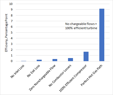
Figure 3: Gas turbine Brayton cycle entitlement stairsteps
Opportunities for improvement
In order to investigate where the opportunities for improvement lie, a sample calculation is done. An advanced class gas turbine with 1,600°C (2,912°F) TIT and cycle pressure ratio of 22:1 (simple cycle efficiency of 41.4%) is taken as the starting point.
For PR = 22, the theoretical efficiency entitlement is 58.7% (with zero losses, isentropic components and no turbine cooling). Going through the elimination of loss mechanisms in an orderly fashion, one ends up with the stairstep chart in Figure 3. The hot gas path provides the largest opportunity for improvement. The improvements in Figure 3 add up to about 12%. Thus, the maximum possible efficiency is 53.4%. The difference between 53.44% and 58.7% is due to the exergy destruction (irreversibility) in the combustor. There is nothing that can be done to alleviate this fundamental loss.
Efforts to minimize the hot gas path losses include:
- Reduction of cooling flows materials (superalloys, ceramic matrix composites), casting techniques (directionally solidified, single crystal), film and effusion cooling, thermal barrier coatings
- Brush and honeycomb seals, and reduced clearances
- 3D CFD for airfoil profiles and vane/blade geometries.
Technologies that can help in this endeavor are additive manufacturing, faster computer processing, data analytics and adaptive controls. The goal of combustor improvements is to achieve stable, premixed combustion for low NOx at 1,700°C. The enabling technology is axial fuel staging. The concept can be thought of as reheat or sequential combustion without a turbine stage between the combustors. The technology also enables the turndown of the GT to low loads while staying emissions-compliant.
Modern axial compressors are also quite close to entitlement with polytropic efficiencies of 93% or higher. Similar to the combustor, the focus of the designer is on stable operation without surge or stall across the entire operating regime (ambient and load conditions).
The enabling technologies are 3D aero design codes and multiple stages of variable stator vanes with model-based (adaptive) controls. As the GTs become bigger and hotter, it is imperative to optimize component size (lower stage numbers and flow-path profiles).
One OEM’s next generation machine has a 12-stage axial compressor with a pressure ratio of 24:1. In addition, OEMs have originated various initiatives and technologies to improve performance. This includes sequential (reheat) combustion, rotor and hot gas path cooling air, steam cooling of hot gas path components, welded rotors, hydraulic clearance optimization, serrated (Hirth) or Curvic coupling of disks and fuel moisturization.
For the bottoming cycle, the status of the technology maturity is such that it allows only incremental improvement at best. As turbine inlet and exhaust gas temperatures creep up, the key thermodynamic design principle is to match source (exhaust gas) and sink (steam) temperatures.
This is primarily a material-and-cost issue. The state-of-the-art is 600°C (1,112°F) in main and hot reheat steam temperatures. At existing steam cycle pressures (as high as 180 bar or 2,600 psi for high-pressure steam), alloy tubes (in the heat recovery boiler) and pipes are required. This adds significantly to construction costs. Even higher steam temperatures are requisite for an optimal match with exhaust temperatures pushing 650°C or higher. Rating performances are typically quoted with minimal auxiliary equipment loads and once-through water cooled condenser (lowest possible steam turbine back-pressure with minimum parasitic loss).
In many places in the world, water scarcity and environmental regulations make this impractical. Another site-specific limit is the stack gas temperature from a plume abatement perspective. On paper, it is possible to design a heat recovery boiler and steam cycle to bring the stack temperature to very low levels. However, even when cost is ignored, it could only be built in a few places in the world.
S. C. Gülen is a Bechtel Fellow and Senior Principal Engineer at Bechtel Infrastructure and Power. For more detailed coverage of the concepts discussed herein, see his recent book Gas Turbines for Electric Power Generation (Cambridge University Press, 2019). For more information, the author will make a presentation at Turbo Expo 2019.


