Evolution of turboexpanders
Conventional turbine technology developed from hydropower, where flow is directed from a higher elevation to a lower elevation, so that the high pressure inlet is located above the low pressure outlet. This configuration is natural when energy is to be extracted from waterfalls and river rapids. For the application of LNG expanders, the fluid power is given by the pressure of the LNG stream, which is practically independent of the elevation.
This article contains excerpts from the paper, "Fifteen years of field experience in LNG expander technology", by Vinod Patel of KBR and Hans Kimmel of Ebara Corporation presented at the first Middle East Turbomachinery Symposium.
The first generation of LNG expanders followed the conventional hydropower design with both flow direction and pressure gradient downward, neglecting the fluid properties of the compressible LNG. When compressible fluids expand convective forces in an upward direction are created. This buoyancy enhances upward fluid flow but impedes downward flow.


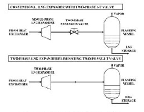
Conventional Single-Phase Versus
Two-Phase LNG Expander[/caption]
In LNG expanders the axial thrust caused by the pressure gradient of the LNG is in the same direction as the LNG flow. In the case of downward flow the thrust force and rotor weight add together, whilst for upward flow the rotor weight is subtracted from the thrust force. The difference of the total net force is therefore two times the weight of the rotor. Since the axial net force has to be balanced by the thrust balancing device using a certain amount of pressurized LNG, this amount of LNG is significantly reduced for the upward flow and increases the overall efficiency.
The upward flow design has a lower centre of gravity than the downward flow design due to the greater weight of the induction generator, with its laminations and copper, compared to the hydraulic part manufactured from cryogenic aluminum. A low centre of gravity reduces vibration and offers additional mounting stability. The advanced design for expanders with upward flow and upward pressure gradient also enables without modifications, expansion of saturated two-phase LNG with up to 10% volumetric vapour content. With some additional components the upward flow expander can expand saturated LNG to higher vapour content, even to 100% vapour. These design modifications are included in two-phase LNG expanders.
This design of LNG expanders are straightforward to maintain. Having fixed geometry, the only moving part is the complete rotor with its induction generator, all mounted on a single shaft. The maximum plant differential pressure determines the maximum rotational, self limiting speed along the zero torque line. Thus there is no ‘run-away’ condition and the design speed is at a margin above this maximum speed. The unique TEM balances the total hydraulic thrust, providing significantly extended bearing life. There are no regular daily or monthly maintenance tasks to undertake, there being no rotating seals or seal system, no oil lubricated bearings or lubeoil system and no actuators or similar ancillaries.
Generator output, inlet and outlet conditions and vibration are monitored, providing a complete picture of the machine’s condition trend in order to plan maintenance. Compared to other designs, routine maintenance is achieved with a degree of ease due to the small size and weight of the components and relatively few ancillary components to maintain or remove before removal of the expander. The simplicity of the expander design, including ease of setting the TEM, enables assembly and disassembly with a minimum of special tools.
Hybrid bearings with steel inner and outer races, silicon nitride balls and molded resin separators have been successfully used to increase bearing life. Their greater resistance to debris and reduced wear in low lubricity liquids shows a significant extension of life. Hydrostatic bearings have been utilizing by the manufacturer and could also be adopted with ‘touchdown’ ball bearings for start‐up and shutdown.
Rotor dynamic studies of hydrostatic bearings at the upper, lower and tail bearing locations show improved separation and damping stability with the entire operating region of the expander shifted to a more conservative area. Endurance testing verifies hybrid touchdown bearings will endure axial forces during start‐up and shutdown with high axial force applied over several hundred start and stop cycles.
In modern refrigeration process plants the liquefaction of natural gas is achieved at increasingly higher pressure and mass flow to improve the overall process efficiency. Trends for future LNG plants are naturally towards larger mass flow and higher pressure to secure the efficiency gains offered. The condensed and highly pressurized LNG is expanded across a liquid-vapour two-phase expander to a lower pressure suitable for storage and transportation of the liquefied gas. This expansion process generates a certain amount of vapour and the remaining liquid is further cooled.
The objective of the two-phase LNG expander is to increase the amount of liquid and to decrease the amount of vapour at the expander outlet. For the conventional process the outlet pressure of the LNG expander is approximately 500 kPa (72.5psia) above the saturation pressure and the remaining pressure energy is throttled across a flashing two-phase J-T valve. For the new process employing two-phase LNG expanders the outlet pressure of the expander is equal to the outlet pressure of the J-T valve in the conventional process. The two-phase LNG expander converts the total available pressure into electrical energy and reduces the enthalpy of the LNG, decreasing the amount of vapour and increasing the amount of liquid.


