Overspeed impeller testing: Follow these guidelines to avoid trips and facilitate successful testing per API 617 standards
By Mark Kuzdzal and Martin Maier
Impeller overspeed testing is essential to ensuring the safety and reliability of centrifugal compressors. To meet API 617 requirements, compressor impellers must be individually balanced and oversped to 115% of the maximum continuous operating speed (MCOS) for one minute.
A centrifugal compressor was recently manufactured for hydrogen recycle service in a continuous catalyst regeneration (CCR) process. During overspeed testing, certain compressor impellers exceeded the overspeed machine vibration limit, resulting in trips.
After further investigation, it was suspected that this event was the result of an inertia dominant resonance condition occurring when the ratio of the polar moment of inertia and transverse moment of inertia approaches a value of one.
Polar inertia (Ip) is the inertia calculated relative to the longitudinal axis. Transverse inertia (It) is the inertia calculated relative to the diametral axis. In the limiting case, for a thin circular disk the ratio of polar-to-transverse inertia is 2.0. This ratio for a solid sphere is 1.0.


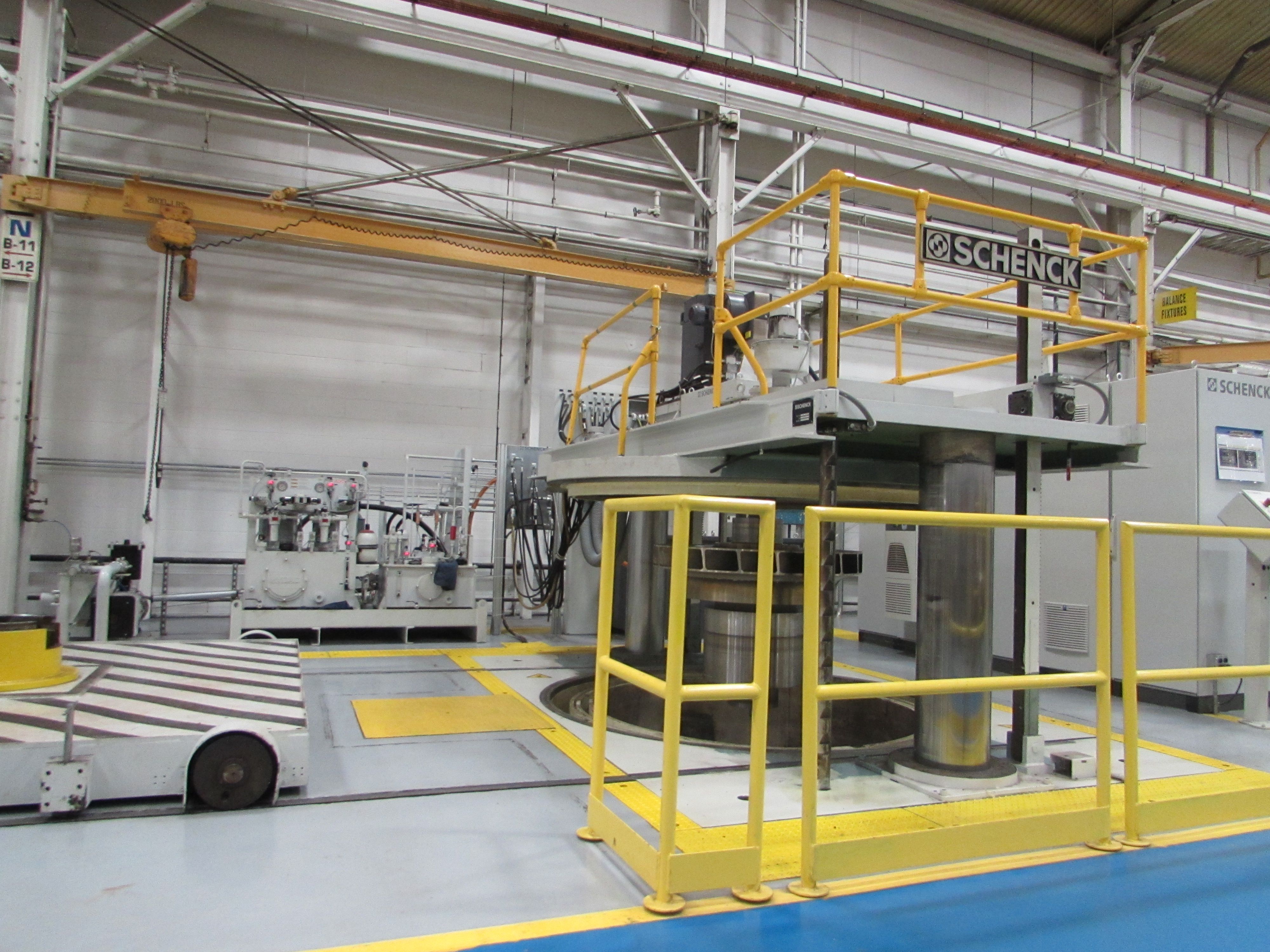
The overspeed test pit. The mandrel assembly is positioned on the cart (far left), which is rolled under the overspeed machine where it is fastened to the spindle. It is lowered into the pit, and a vacuum pump evacuates the chamber to minimize the power required to drive the impeller and heat generation associated with windage.[/caption]
Testing process
The centrifugal compressor had a radially split, beam-style, five-stage, straight-through design. A steam turbine was used to direct drive the compressor at 5,026 RPM. The impellers were balanced to API 617 8th Edition (ISO 1940/1 G0.67). This was accomplished before each run in the overspeed machine.
The overspeed machine used for testing can be outfitted with various mandrels (fixtures or shafts that retain impellers when mounted on the spindle of an overspeed machine) to accommodate different sizes of impellers and speeds. The machine continually measures vacuum pressure, speed, and vibration during the test. The latter is measured with a proximity probe.
The unit is designed to trip and shut down when a maximum vibration of 8.0 mils is reached. This is referred to as 100% full scale (FS) amplitude. The machine uses rolling element bearings with a squeeze film damper bearing in series. A key phaser was added to enable rotor dynamics analysis investigation. A 150 HP (112 KW) main drive motor is connected to the mandrel via a belt drive.
The shafting is oriented in a vertical direction, and a ‘bumper’ bearing is located on the bottom of the machine. The mandrel is manufactured so that a pin is located at the bottom of the mandrel. During mandrel installation, the pin fits inside the bumper bearing with a 0.020-inch (0.51 mm) clearance. This limits the motion of the mandrel and impeller in the event of excessive vibrational amplitude.
Historically, it has been the practice at Siemens to use the same mandrel on a given testing job for both balancing and overspeed of an impeller. As a result, the mandrel must be designed to the length of the overspeed machine and be capable of withstanding the bending moment of the impeller mounted on the machine during balance. This can result in a rotor system where the ratio of the polar (Ip) and transverse moment (It) of inertia approaches a value of 1.0.
The manufacturer of the overspeed machine provides operational guidelines based on these parameters. It states that Ip/It ratios between 0.70 -1.20 should be avoided due to the likelihood of high vibration.
Initial testing
During initial overspeed testing of the 3rd stage impeller of the compressor, the rig tripped out due to high vibration at a speed of approximately 4,800 RPM. The impeller was run with a multi-piece, built-up mandrel with the impeller shroud facing upward. The overspeed requirement for the impeller was 5,780 RPM.
Vibration exceeded the classic speed-squared trend relationship. This indicated that the increase in vibration was the result of more than just the system’s response to a fixed amount of unbalance.
A static bump (or ring) test was performed immediately following the test with the mandrel suspended vertically in the overspeed machine. This was done to determine if there was a resonance in the vicinity of 4,800 RPM. However, it was later discovered that it was not responsible for the observed vibration excursion.
Further investigation looked into whether the vibration trip event was the result of an inertia dominant resonance condition, as the Ip/It inertia ratio was outside the recommended operating limits documented in the overspeed machine operator’s manual. In this case, the Ip/It inertia ratio was 1.05. It became evident that it was necessary to understand the phenomenon more clearly to determine the best way of addressing it.


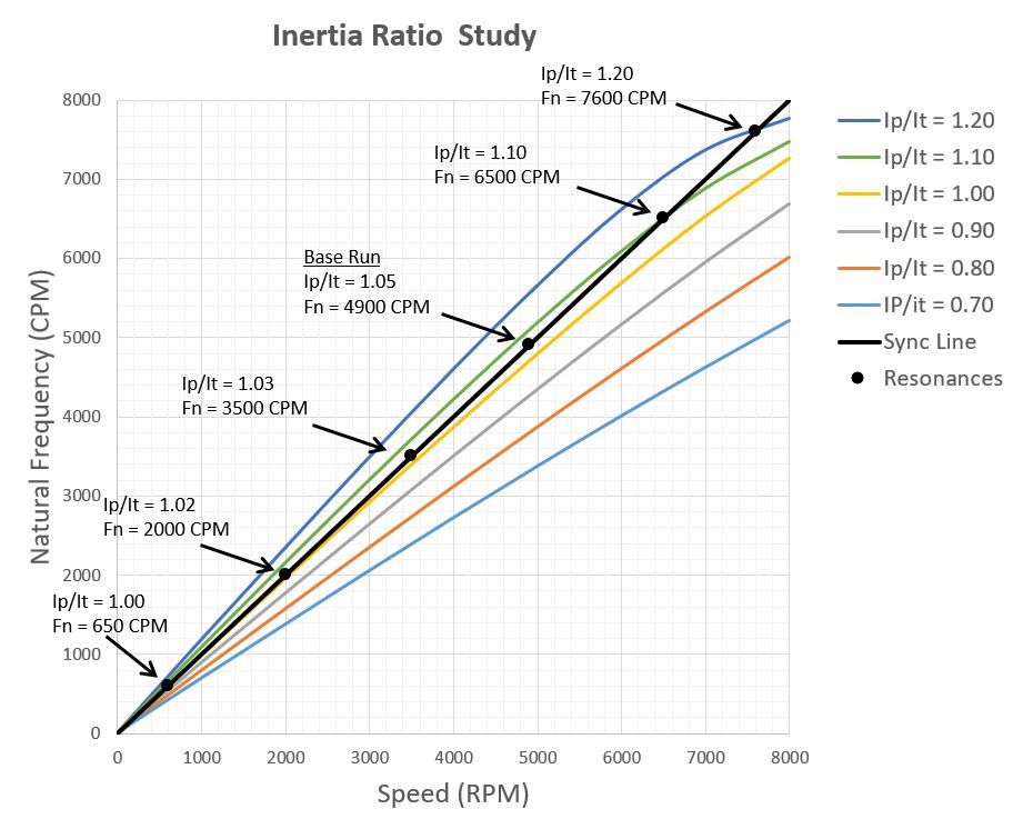
Damped Eigenvalue Plot for mandrel assemblies showing curves for Ip/It inertia ratios ranging from 1.20 - 0.70. The resonance frequencies (intersections with the synchronous speed line) change rapidly as the inertia ratio is reduced from 1.10 to 1.0, so this region should be avoided. For inertia ratios below 1.0, the resonance frequency is in the 100 cycles per minute (CPM) to 300 CPM range.[/caption]
Theoretical basis
An inertia study was performed. The separation distance between the disks was varied to change the transverse inertia and associated Ip/It ratio. It is evident that the natural frequency for inertia ratios close to 1.0 is sensitive to small variations in modeling, boundary conditions, and assumptions. For this reason, operation at inertia ratios between 1.0 - 0.95 should also be avoided.
Two different approaches were explored to address the vibration issue and successfully achieve overspeed. The first involved the possibility of accelerating rapidly through the resonance with the existing mandrel design.
A parametric study was performed to determine if it was possible to accelerate (and decelerate) through this mode at such a rate to prevent the vibration from building to unacceptable levels. The rationale being that the greater the acceleration rate, the less time the system could absorb energy and amplify. This was not feasible due to the practical limits of the overspeed machine and levels of residual unbalance present in the mandrel assembly.
The second approach involved modifying the mandrel inertia ratio to shift the resonance outside of the range of operation. This was determined to be the best route forward. To avoid disruptions to the production schedule, two modification options were pursued simultaneously.
The first option, which was associated with a shorter lead time, involved installing a flywheel on the existing mandrel to increase the inertia ratio above 1.20. The second was to redesign the mandrel to a one-piece component with an inertia ratio below 0.70. Doing so, however, would result in longer lead time.
Flywheel testing ultimately proved to be unsuccessful due to problems associated with repeated vibration during start-up and shutdown. However, during testing, it was noted by shop personnel that, in some instances, impellers ran better when they were mounted with the shroud facing downward. As the newly designed mandrel was not yet available for testing, this suggestion was noted and tested. The flywheel was then removed, and the impeller mounted on the existing mandrel with the shroud facing downward.


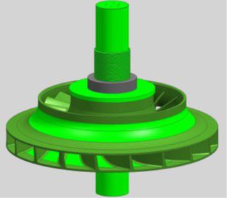
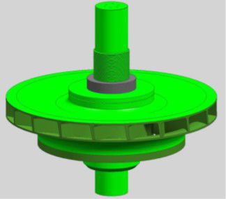
Impeller shroud facing up (top) and impeller shroud facing down (bottom).[/caption]


With the impeller shroud facing down, the rotor assembly successfully reached overspeed. One factor that may account for this result is the Ip/It inertia ratio. It increased from 1.05 to 1.13 after flipping the impeller. Another factor is the residual unbalance. It may have shifted closer to the mandrel’s center of gravity. Rotor dynamic calculations indicate that if the unbalance shifts by a little as 1.0 inch (25.4 mm), such that it coincides with the mode’s pivot point, the system response is virtually eliminated.
Eventually, the second (preferred) option could be implemented, as the new mandrel was manufactured and available for use for overspeed testing of the 2nd stage impeller. The new mandrel was designed such that the Ip/It inertia ratio of the mandrel assembly was reduced from 1.13 to 0.68. All subsequent impeller overspeed tests were successful with the new mandrel.


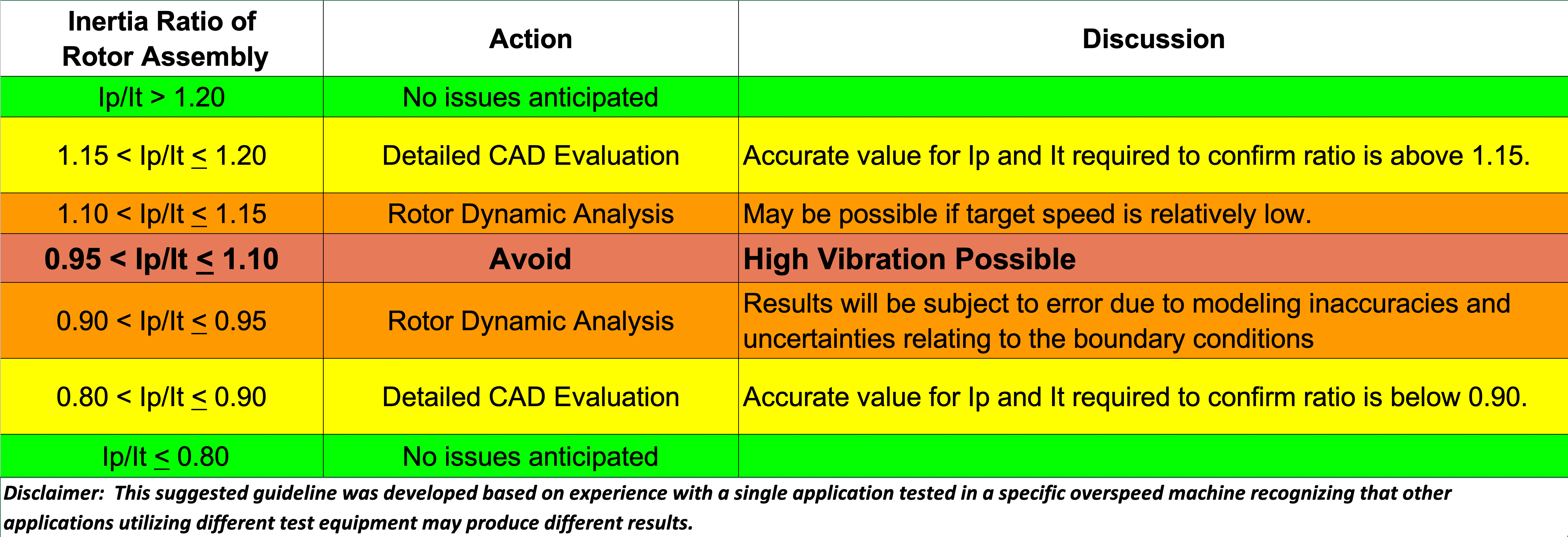
Insertia ratio guidelines.[/caption]
High shaft vibration
In centrifugal compressors, therefore, an inertia dominant resonance condition can occur. This results in high shaft vibration when the ratio of a rotor system polar moment of inertia and transverse moment of inertia approaches a value of 1.0. Impeller overspeed testing is a likely place for these inertia values to converge.
Attempting to balance out this resonance condition or accelerate rapidly through it has a low probability of success and can result in equipment damage. This is mainly based on the torque transmission limitation of the belt drive system to both accelerate (run-up) and decelerate (brake) the mandrel assembly, especially with large impellers. Suggested guidelines are available to assess the level of risk when operating near this resonance condition.
The probability for success when operating near the 0.95 < Ip/It <1.10 inertia ratio range improves if the following guidelines are observed:
- Align the center of gravity of the impeller close to the pivot point of the rigid body mode. The pivot point is near the CG of the mandrel assembly. This will help to reduce system response. installing the impeller on the mandrel with the shroud facing down resulted in a successful overspeed run, albeit not conforming to the overspeed machine manufacturer’s Ip/It guidelines.
- Confirm that the component fits are sufficient to remain engaged to maintain concentricity throughout the speed range.
Our analysis shows that the observance of these suggested guidelines promotes successful overspeed testing per API 617 standards.
______
Mark Kuzdzal is the R&D Head for the Advanced Components and Methods group at Siemens Gas and Power, the global energy business of the Siemens group. Siemens.com/energy
Martin Maier is a Principal Rotor Dynamic Analysis Engineer at Siemens Gas and Power. For more information, “A Resonance Condition Encountered in a Shop Overspeed Machine Due to Inertia Effects: The Theoretical Basis and Practical Experience,” 48th Turbomachinery Symposium by Maier, M., Barnes, T., Frier, S. Kuzdzal, M., 2019.
Newsletter
Power your knowledge with the latest in turbine technology, engineering advances, and energy solutions—subscribe to Turbomachinery International today.


