Selecting screw compressors


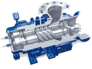
Cutaway of an oil-free screw compressor with dry gas mechanical seals[/caption]
A screw compressor is a twin-shaft rotary piston machine functioning on the principle of positive displacement combined with internal compression. The medium handled is conveyed from the suction port to the discharge port, entrapped in steadily diminishing spaces between the convolutions of the two helical rotors, being compressed up to the final internal pressure before it is released into the discharge nozzle.
This article is an excerpt from the paper, “Your Gas Compression Application – Reciprocating, Centrifugal, or Screw?” presented by Greg Phillippi of Ariel Corporation, Tim Manthey of Aerzen USA, Jonathan Sutter of Elliott Group, Ben Williams of Ariel Corporation and Bruce McCain, an engineering consultant.
The spaces referred to are those formed between the cylinder walls and the interlocking convolutions of the two helical rotors. The position of the edge of the outlet port determines the so-called “built-in volumetric ratio”, Vi.
The compression that occurs internally in the compressor is isentropic: the volume is being reduced. The compression that can occur in the discharge header is isochoric: more gas is being pushed into a fixed volume. Since a screw compressor operates on a positive displacement principle, it will continue to move the same volume of gas per rotation regardless of gas density and downstream pressure. The screw compressor rotor is stiff and has a low moment of inertia. Precision balancing is not as critical and the operating range will normally be below the first torsional critical speed.
Screw compressor pressure limits are normally dictated by temperature, due to the heat of compression; however, rotor deflection and bearing life are also key factors in pressure limits. In an oil-free screw compressor, sometimes referred to as a “dry” screw, the rotors do not contact one another, but are separated with extremely small clearances via timing gears. Seals at the conveying chamber ensure that the conveyed gas does not come into contact with the lubricating oil or outside air. Thus, the gas is never contaminated by the oil, and vice versa.
In an oil-injected screw compressor, sometimes referred to as a “flooded” or “wet” screw, there are no timing gears. Rather, one rotor drives the other directly. There are also no internal seals. The conveyed gas is mixed with the lubricating oil inside the machine, and gas and oil are discharged together. The oil is then separated from the gas stream before the gas is discharged into the downstream system. The oil is then cooled, filtered, and again injected into the compressor conveying chamber, bearings, and driveshaft seal. Because the gas is mixing with the oil, care must be taken in oil selection to prevent oil contamination by the gas or gas contamination by the oil. Capacity control is possible via an internal slide valve.
Flooded screw compressors are often considered for applications with low suction pressure and a relatively clean gas, especially when a small footprint is desired. Flooded screw compressors are often selected over dry screw machines when a large compression ratio and single casing is needed. High compression ratio, and resulting high heat, requires a synthetic lubricant be used to seal the clearance in the screws and provide cooling.
Dry screw compressors operating at higher temperatures may need special casing metallurgy. However, dry screw compressors are more suitable for dirty gas services, high water content, or has other properties that would contaminate the oil of a flooded screw.
For oil-flooded screws, accurate gas composition is critical so the correct lubricant can be selected. If the gas composition changes before or after startup, this must be addressed immediately to minimize risk of lubricant carryover and/or impact to machinery health. Oil-flooded screw compressors in upstream oil and gas service typically utilize a synthetic oil.
In some services, the large expenditure for synthetic oil may be offset by lower frequency of oil replacement. Oil usage and costs should be taken into account when performing life cycle cost analysis: both initial fill and subsequent oil replacement.
Some end users have been guilty of only looking at unit cost (per gallon) comparisons of synthetic and mineral oils. Synthetic oil unit costs may be more expensive, but the entire operation must be looked at.
Mineral oil may breakdown faster, resulting in a significantly higher volume of mineral oil being used. The end user should also be aware that this premature breakdown could result in more maintenance requirements for the compressor. For these reasons, detailed discussions should be had with the screw compressor manufacturer and operations personnel during the selection process.
Volume ratio, Vi, should always be considered when evaluating screw compressor applications. Vi along with the ratio of specific heats (K), determines the internal pressure ratio. Departure from the design Vi for gases should be understood before selecting a specific machine. If the volume ratio is too low for the system operating pressure, then under-compression will occur.
Under-compression is an event where the gas being compressed in the screw thread nearest the discharge port does not reach the actual discharge piping pressure. As soon as that volume of gas is exposed to discharge piping pressure, a pulsation occurs from the discharge piping into the discharge port. If the volume ratio is too high, then over compression will occur. In this scenario the pressure at the discharge port is higher than the discharge piping pressure.
As soon as the gas is exposed to the discharge port, a pressure pulse moves from the screw thread towards the discharge piping, thus equalizing pressure. Both under-compression and over-compression will require more power to move the gas. Since most screw compressors have a fixed Vi, this is often unavoidable, so the key is to select Vi for the normal running condition. Additionally, both events will cause gas pulsations and will typically have the greatest amplitude at the Pocket Pass Frequency (PPF). This attribute is potentially damaging: the pulsations can mechanically couple with piping and generate vibration. If coincident with piping mechanical natural frequencies, then amplification can occur resulting in very large vibration amplitudes and resulting stresses on nozzles and attachments.
The design of the piping should take into account the Pocket Pass Frequency. Piping supports and clamps should impart the appropriate stiffness to allow required separation margin between excitation and mechanical natural frequencies.


