
|Articles|January 27, 2017
Components of a gas turbine enclosure
Author(s)TMI Staff & Contributors
Advertisement
In a fully enclosed gas turbine installation, the enclosure sides and roof include panels and access doors supported on a heavy-duty frame. The side and roof panels are easily removed individually for complete access to the major components for inspection and maintenance and for component removal by forklift and overhead crane. The panels are treated with fiberglass material for noise attenuation and thermal insulation, and weather stripping is installed between all panels for sealing and sound attenuation.
This article contains excerpts from the paper, “Gas turbine packaging options and features” presented at the Second Middle East Turbomachinery Symposium by Klaus Brun of SouthWest Research Institute, Rainer Kurz of Solar Turbines and Marybeth G Nored of Apache, Inc.
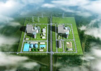
Fully enclosed gas turbine installation[/caption]
The enclosure is constructed to support adequate roof load (usually 50 lb/sqft) and to withstand a wind load of 120 mph (or more, if specified). The following standard features are usually included in a basic enclosure:
- Inlet and exhaust ventilation silencers: The enclosure ventilation openings are equipped with vent silencers with weather louvers.
- Single fan ventilation system: Enclosure ventilation is provided by a single motor-driven fan. This motor is typically 3-phase AC, high efficiency, with Class F insulation. The fan is sized to provide the airflow required to ensure that the internal air temperature arounGasd the enclosed equipment remains within acceptable limits. Sometimes, for additional ventilation or certification requirements, a dual fan ventilation system may be required.
- Pressurization system: The enclosure is positive pressurized to prevent the ingress of external hazardous atmospheres through the enclosure seams. A differential pressure transmitter is provided for enclosure low pressure alarm and shutdown.
- AC lighting: 110-VAC or 220-VAC lights are provided to illuminate the enclosure interior, with on/off switches located at the interface panel.
- Trolleys: Internal movable trolley rails located over the turbine for turbine maintenance and removal are included.
- Door Hardware: All enclosure doors are equipped with a heavy duty stainless steel door locking mechanism, including handles, hinges, latching mechanism, internal lock override release, restraining device, and attaching hardware. The enclosure doors are equipped with door position switches to initiate an alarm whenever any of the enclosure doors are not securely closed.
Computational Fluid Dynamic (CFD) tools are used in both on- and off-shore applications to validate design criteria. Previously, this data was only occasionally requested for offshore applications. Now, however, it is becoming more of a requirement. We will focus on the application of this tool for the acoustic enclosures. The CFD tool is used to apply the surface temperature to the turbine, understand the temperature distribution within the enclosure, and determine the required flow distribution and proper size of the ventilation fans and motors. Understanding the flow distribution within the enclosure allows the optimization of the package design to minimize stagnant volumes where gas, if present, could be trapped, as well as position package components away from identified hot areas so the component temperature limits are not exceeded.
The test rig is used to match the analysis with actual test data to validate the accuracy of the CFD tool. The colored streamlines represent airflow velocity throughout the enclosure with dark blue representing the lowest velocity flow and the light blue, green, and yellow representing progressively higher velocities. This CFD model represents a full size package with all of the major components. The dashed lines represent the flow direction. Again, the dark blue color being the lower velocity air; while green, yellow, and red represent increasing velocities.
Beyond the above described features, manufacturers often provide the following options for the enclosure:
Sound Attenuation
The sound-attenuated enclosure is intended for use with suitable turbine air inlet and exhaust silencing systems in environments where low noise levels are a requirement. Ventilation openings are equipped with suitable silencers to achieve maximum sound attenuation. Sound levels at a specific site will depend on existing walls, barriers, equipment in close proximity, multiple units, and other installation considerations.
Enclosure Barrier Filter
The enclosure ventilation inlet is equipped with a singlestage, disposable, barrier-type filter unit equipped with a deltaP alarm switch. The ventilation exhaust opening is equipped with back-draft dampers to prevent ingress of dust when the unit is not running.
Fire and Gas Detection and Monitoring System
Usually, an automatic, electronically controlled fire and combustible gas detection and monitoring system is installed in the enclosure. A typical system description is provided below: The primary fire detection system uses multi-spectrum infrared (MIR) detectors. The system includes an automatic optical integrity feature to provide a continuous check of the optical surfaces, detector sensitivity and electronic circuitry of the detector-controller system, and automatic fault identification with digital display of system status in numerical code.
The secondary fire detection system consists of rate compensated thermal detectors. The two detection methods act independently in detecting and reporting a fire. The fire and gas system control panel provides system supervision (for open circuit, ground fault, or loss of integrity), initiates alarm, release of fire suppression agent, and visual display of system status. The suppression system agent release is activated automatically with release solenoids located on the fire suppression skid. The suppression system can also be activated by an electrical push button on the turbine enclosure or manually at the suppression skid. If a fire is detected, the detectors transmit an electrical signal to the fire and gas system control panel to activate the fire alarm and suppression system. The enclosure is equipped with two gas detectors: one at the turbine enclosure ventilation air inlet and one at the ventilation exhaust to provide continuous monitoring for combustible gases at the enclosure ventilation inlet and outlet.
The detectors are diffusion-based, point-type infrared devices that provide continuous monitoring of combustible hydrocarbon gas concentrations. The turbine start signal is interlocked with the fire and gas monitoring system to ensure the atmosphere is safe prior to initiating turbine engine start.
Most commonly, the enclosure is equipped with a CO2 fire suppression system consisting of a primary total flooding distribution system and a secondary metered distribution system. In the United States, the system is designed in accordance with the U.S. National Fire Protection Association Code 12. On detection of fire, the detectors transmit an electrical signal via the fire control panel to activate the fire suppression system release solenoids located on the fire suppression skid. On receipt of this signal, the solenoid actuated control heads activate the discharge valves on the primary and extended extinguishing cylinders, releasing the extinguishing agent into the enclosure.
CO2 pressure actuates the pressure trip operated dampers that close all vent openings. CO2 release control heads are also provided with manual release levers.
Additionally, a weatherproof fire suppressant cylinder cabinet is sized to house the CO2 extinguishant cylinders and is equipped with doors for servicing. The manual pull levers are routed, by cable, to break glass pull stations on the exterior wall of the cabinet. CO2 cylinders are mounted on a weight scale with a preset alarm.
Another frequently used fire suppression system uses water mist.
Equipment Handling System
An equipment handling system is provided, consisting of external trolley beams and movable chain-fall hoists for removal of major equipment from the package. A trolley beam extension allows turbine removal through the side of the enclosure. One end of the beam extension attaches to the inside trolley rails; the other end is a floor-standing A-frame. The gas turbine or other heavy equipment is then removed through the enclosure side and placed on a truck bed or cart.
Advertisement
Related Content
Advertisement


Advertisement
Advertisement