
|Articles|July 1, 2013
FOGGING WORKS IF DONE CORRECTLY
Author(s)TMI Staff & Contributors
Advertisement
INSTALLATION OF FOG INVOLVES ADHERENCE TO BEST PRACTICES, SUCH AS AVOIDING LARGE DROPLETS AND LOOKING BEYOND AVERAGE DROPLET CALCULATIONS
Gas turbines are precision machines and require precisely designed and configured ancillary equipment. When inlet fogging causes a problem, it is usually a case where the system produces large droplets instead of a true fog. If the droplets are too big, they will not fully evaporate in the inlet air stream.
Fog systems work by injecting a spray of liquid water droplets into the inlet air stream. Their evaporation cools the air, which increases air density and leads to increased turbine output and improved fuel economy. For maximum power boost, droplets must evaporate quickly.
From the instant water leaves the nozzle orifice, it only resides in the airflow for one to two seconds before reaching the compressor inlet. If it fully evaporates, or the droplets are small enough, there is no damage potential. Larger droplets can, however, lead to blade erosion, particularly on the R0 blades.
Since evaporation only occurs at the water-air interface, the rate at which a droplet evaporates depends upon the ratio between its mass and surface area. Even a slight increase in diameter results in large increases in mass.
Since a droplet’s mass increases as the cube of its diameter, a twenty-micron droplet has eight times the mass of a ten-micron droplet (2x2x2), a thirty-micron droplet has 27 times the mass (3x3x3) and a fortymicron droplet has 64 times the mass (4x4x4). In addition, larger droplets result in a lower aggregate surface area compared to the same mass of water is broken into smaller droplets. Thirty-micron droplets, for example, have one-third less total surface area than the same volume of water broken into twenty-micron droplets.
Experts generally agree that a fog system should produce droplets with a diameter of 20 microns or less since these will evaporate quickly enough to provide maximum cooling before the air reaches the compressor inlet. Smaller droplets are also more able to follow the air as it flows around silencer panels, structural elements and trash screens.
All droplets produced by a fogging system will not be the same size, however. Even if they were the same size, given the inlet airflow characteristics, they will not evaporate at exactly the same rate. As a result, there will always be some fog droplets that enter the compressor.
Computational Fluid Dynamic (CFD) modeling shows that droplets under about 10 microns are small enough to follow the flow lines around compressor inlet guide vanes and blades, thus eliminating the possibility of blade damage. It is likely that compressors can tolerate larger droplets than 10 microns without sustaining damage but just what the maximum acceptable droplet size is, remains an unknown. These sub-10 micron droplets, however, will fully evaporate during compression, providing a further power boost. This technique is known by various terms such as overspray, intercooling and wet compression.
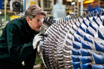
Blade surface erosion
Larger droplets do not fully evaporate and are more likely to impact and erode the compressor blade surfaces. In addition, since they are heavier, they are more likely to fall out of the air stream and pool on the surfaces of the inlet ducts. This pooled water then gets sucked in through the bell mouth producing further damage.
When evaluating a fogging system, the average droplet size is irrelevant and misleading. If a fogging system produces one 50-micron droplet and 1,000 5-micron droplets, the average size is 5.04 microns. However, that large droplet has the same mass as 1,000 droplets of 5 microns.
Chaker et al suggested two more useful measurements.* One is the Sauter Mean Diameter (SMD) D32 which is based on the ratio of surface area to volume and shows how quickly the water can fully evaporate. The other, known as DV90, shows that 90% of water volume consists of droplets smaller than the given figure. A DV90 of 30 microns means 90% of the water is broken down into droplets no larger than 30 microns. Producing optimal droplet sizes depends on factors, such as nozzle type, nozzle array design, water pressure and orifice size, as well as looking at the SMD and DV90 figures.
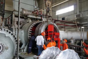
A Latin American combined cycle plant with four Siemens W501 D24/D5 gas turbines had installed low-price fog systems on all four units. The plant initially exceeded a 10% power increase. However, after detecting an unusual noise in Unit 2, inspection found a fog spray nozzle had broken, damaging blades on Stages 1 through 19, which were then repaired.
A few weeks later, the unit suffered a catastrophic failure. Operators discovered shredded blades and diaphragms. A Unit 5 inspection also revealed premature erosion and material removal from compressor blades. By the paths traced on the blades, it appeared that droplets impacted blades up to Stage 8. Poor nozzle placement and a 90 degree angle in the inlet duct caused droplets to agglomerate, collect on the spiral baffle and get sucked into the inlet.
Rather than eliminate fogging, the utility upgraded to a correctly built system consisting of 890 impaction pin nozzles with a 127 micron orifice and operating at 207 bar (3,000 psig). Each nozzle produced a flow of 0.162 l/min for an aggregate maximum water flow of 144.2 l/min. The system was designed to produce 11°C cooling +0.4% overspray with 13 cooling stages.
A 40 MW power increase was achieved. By implementing best practices on system design and droplet size, inspection had verified that erosion issues were no longer present after two years of operation.
Research is covered in three papers presented at the ASME Turbo Expo 2002 by Mustapha Chaker and Cyrus B. Meher- Homji (both currently at Bechtel Corporation), and Thomas Mee III of Mee Industries, Inc.
Author
Eric Adamson is a manager at Mee Industries and has 15 years experience in building fog- based cooling systems. Since 1990, the company has installed over 800 gas turbine inlet cooling systems in power plants, processing plants, and generation stations worldwide. For more information, visit www.meefog.com.
Advertisement
Related Content
Advertisement

Advertisement
Advertisement