FUEL GAS REQUIREMENTS FOR AERODERIVATIVE GAS TURBINES
HIGH PRESSURE SINGLE SCREW COMPRESSORS EXPAND OPTIONS FOR FUEL GAS PRESSURE BOOSTING
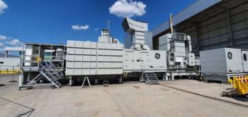
Once considered an occasional “necessary evil,” fuel gas booster (FGB) compressors in turbine power generation facilities have become a common requirement. FGBs are installed because of insufficient gas pressure onsite or from nearby utility gas pipelines (Figure 1). Historically, pressures up to 300 psig (~20 barA) were adequate for most industrial gas turbines and were often available onsite or at an economical distance. But modern gas turbines tend to run at much higher compression ratios, thus raising the inlet fuel gas pressure requirement.
Aeroderivative gas turbines, for example, can require inlet gas pressures that exceed 900 psig (~60 barA) to operate efficiently. To meet these higher gas pressure needs, a FGB compressor can be deployed to raise and ensure adequate fuel gas pressure for the turbine. The requirements of these compressors are a wide turndown range and the ability to handle supply gas pressure fluctuations, while delivering constant discharge gas pressure to the turbine fuel system. In addition, FGB compressor systems must be able to deal with turbine load changes (part load or start-up) and gas composition changes which alter flow rate needs.
Compressor options
Gas turbines are frequently matched with a fuel gas booster compressor. Centrifugal compressors were first used for low compression ratio requirements and were popular for a variety of reasons. For instance, they required lower maintenance because of lack of wearing parts, lighter weight design of their rotating parts and because their gas filter and oil filter were easily maintained and replaced.
Other advantages included being almost free of pulsation and vibration. On the downside, centrifugal compressors do not respond well to changing gas supply conditions or gas turbine load reductions because of limited capacity control. Also, high first costs forced operators to consider other compression options.
Reciprocating compressors gained popularity because of their efficiency and ability to deal with changing loads better than a centrifugal compressor. They also boost gas pressures higher than centrifugal compressors. This technology unloads in steps down to 25%. But reliability is not as high as a centrifugal compressor and maintenance requirements are greater. Further, they may need two stages to reach higher pressures.
An alternative approach to turbine fuel gas boosting is the application of oil-flooded twin screw compressors, which have improved reliability, smaller space requirements, and operate with low-vibration and gas-pulsation levels. Screw compressors can also meet turbine pressure requirements in one stage.
When first introduced, screw compressors tended to be noisy with unacceptably high frequencies. Installations had to take into account package vibration and added sound attenuation measures were often needed. They also required complicated oil management systems to prevent oil dilution. And the oil system often included gas pre-treatment, oil separation, oil filtering and monitoring.
More recent single-screw compressor designs have been upgraded with thicker and stronger steel housing to handle higher pressures (Figure 2). This enhancement allowed users to utilize attributes such as no net radial or axial forces exerted on the main screw or drive shaft caused by the work of compression.
Since the compression process occurs symmetrically and simultaneously on opposite sides of the screw, the compression forces are canceled out. Gravity is the only vertical load exerted on the main screw bearings. Since the discharge end of the screw is vented to suction, the suction gas pressure is exerted on both ends of the screw resulting in balanced axial loads. These single-screw compressors can produce pressures up to 950 psi and have a wide suction pressure range.
Single screw compressors with a dualslide design have two slides for each compression side of the main rotor. The two slides are commonly referred to as the capacity slide and the volume slide. The capacity slide moves from positions of 10% to 100% of flow, allowing the compressor to match the system flow requirements and remain energy efficient. This enables high energy efficiency across all operating and part-load conditions. At 25% capacity, for example, the single screw with slide system uses 20% less power compared to a typical twin screw compressor.
Even with recent design enhancements, screw compressors are still not the most economical choice for the highest flow applications, even though some users deploy multiple compressor systems to share the fuel gas flow delivery. While multiple screws in parallel are designed to provide some level of redundancy and turn-down capability, they usually require more capital expense, control complexity and physical installation costs.
Compared to older industrial gas turbine ratings, newer higher compression ratio types (aeroderivative) have tighter and more demanding fuel gas operating requirements. Accordingly, fuel gas booster systems must be capable of efficient operation under varying operating conditions, including gas supply pressures and flow variations because of load.
Reciprocating, centrifugal and screw compressors all have their place. End users must determine what factors are most important to them, such as: maintenance requirements, weight, vibration levels, noise levels, flow rates, reliability, ability to handle changing load requirements, ability to boost pressure to high levels and costs, and then select the type of compressor that best meets their individual fuel gas boosting requirements.
Author
Mark McCormick is Business Director for Gas Compression at Emerson Climate Technologies. His 18-year background with Emerson includes roles in engineering, manufacturing technology, product planning, marketing and general management. He can be reached at mark.mccormick@emerson.com, or at +1.937.493.2844.
Newsletter
Power your knowledge with the latest in turbine technology, engineering advances, and energy solutions—subscribe to Turbomachinery International today.


