
|Articles|September 1, 2012
MATCHING GAS TURBINES AND CENTRIFUGAL COMPRESSORS
Author(s)TMI Staff & Contributors
Advertisement
THE CORRECT ARRANGEMENT INFLUENCES OPERATING COSTS AND FLEXIBILITY IN MEETING PROCESS REQUIREMENTS
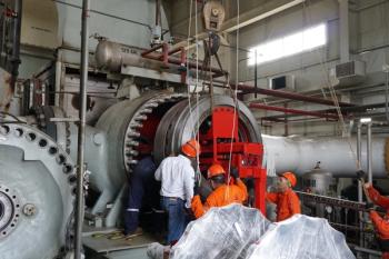
Multiple-shaft gas turbines as drivers of centrifugal compressors are widely used in the oil and gas industry. While gas turbines are of standard design, centrifugal compressors are precisely designed and manufactured to meet customer specific process requirements.
Complete package efficiency, turbine fuel consumption, time between overhauls, and the package flexibility in meeting alternate process requirements are to a large extent influenced by proper integration and matching the centrifugal compressor to its gas turbine driver.
Although there may be very few applications in which a centrifugal compressor may be required to operate in a single operating point, the majority of applications require operation within a specified operating envelope comprised of several operating points at different speeds and various power levels.
The gas turbine should be able to provide adequate power for any and all compressor operating scenarios that may be anticipated during project life. Moreover, the power range and speed range of the gas turbine, which is of standard design, should be well matched with the specified required power and speed range of the centrifugal compressor for all the operating points in the operating envelope.
A clear definition of all the possible operating conditions for the centrifugal compressor, therefore, as well as specifications of the required performance curve characteristics, will assist the vendor to comprehend specific application requirements.
Duty cycles
Gas turbine-driven centrifugal compressors are broadly employed in the oil and gas industry for semi-constant or variable compression duty applications as depicted in Figure 1. Semi-constant duty services tend to fall between two operational extremes: Narrow speed range or narrow flow range and power. Examples may be found in downstream applications such as refrigeration compressors in LNG plants.
Variable compression duty services, on the other hand, include those for which the gas composition, throughput, and process conditions, such as temperatures and pressures, are variable and create a broad range of operating conditions thatmust be accommodated during the compressor’s lifetime.
These variations may be temporary and may follow repeatable patterns due to seasonal demands in gas transmission, or may be permanent change from one operating point to another. Gas gathering and gas lift applications are common examples of variable compression duty services.
A centrifugal compressor, then, may be designed to operate at different operating points during its lifespan. Any change in process conditions, such as temperature, pressure, gas composition and throughput will lead to a new operating point.
Since it is not technically feasible to operate a centrifugal compressor at the same peak efficiency for all these operating conditions, the customer should specify a normal operating condition. As defined by API 617, a normal operating point is an operating point where usual operation is expected and optimum efficiency is desired.
A centrifugal compressor should be designed to provide the required head at the specified flow rate with the optimum efficiency at the normal operating point. For a definite number of specified operating points, API 617 defines the “rated point,” as a virtual point on the 100%speed curve with the highest specified capacity.
The rated point is not a real operating point and should not be considered as a design point. Sometimes, it is employed as an index for the compressor maximum power requirements. Figure 2 illustrates the location of the normal operating point, and the rated point R created for the set of specified operating conditionsA, B, and C.
Among various design parameters for a centrifugal compressor, compressor speed has an immediate influence on number and geometry of impellers, casing size, rotordynamic, efficiency, and operating range. For a specific application, rotordynamics, aerodynamics, or strength of material may limit the compressor design speed.
When the driver is a gas turbine, optimum power turbine speeds at site conditions as well as optimum power margin required for a future-oriented design may be also considered as another parameter in selecting the compressor design speed.
At each power level, there is an optimum power turbine speed range which represents the minimum heat rate and maximum efficiency. For a specified power level, the turbine may run faster or slower than its optimum speed at a cost of lower efficiencies and higher heat loads.
Power turbine speed, after all, is dictated by the driven equipment (centrifugal compressor), and is independent of the gas generator speed. Accordingly, a good design practice is to match the centrifugal speed (normal operating point) as close as possible to an optimum power turbine speed.
API 616, 5th edition, defines the gas turbine site-rated power, as the shaft power developed by the gas turbine when it is operated at site-rated firing temperature, rated speed, normal fuel composition, and site-rated conditions. It must be noted that the gas turbine rated point at the site-rated condition does not have any relation with the centrifugal compressor rated point as defined byAPI 617, 7th Edition.
As mentioned earlier, the power range and speed range of the gas turbine should be well matched with the specified required power and speed range of the centrifugal compressor. API 616 requires that the gas turbine shall be designed for continuous service at each point of the specified speed range and power range including potential maximum power.
Figure 3 depicts the gas turbine operating envelope at site-rated conditions illustrating the gas turbine operating point corresponding to the centrifugal compressor normal operating point. As shown, the closer the compressor operating point is to the optimum power turbine speed, the more efficient the complete gas turbine compressor package will be.
Turbine speed as dictated by the centrifugal compressor load may not be close enough to its optimum value when running at the specified site ambient conditions. One possible solution, when adjustment of turbine nozzle geometry is available, is to shift the optimum power turbine speed to values closer to the centrifugal compressor operating speed.
Optimizing the turbine speed could be achieved by adjusting the turbine nozzle area. In practice, however, few gas turbine vendors offer variable turbine nozzle geometry. Alternative approaches could be selecting the compressor design speed to be as close as possible to the power turbine optimum speed or employing a gearbox.
Gas turbine power varies with site conditions, output speed, inlet and exhaust losses, and degradation. Adequate margin between the compressor required power and gas turbine available power at site conditions must be considered, accounting for gas turbine and load compressor performance degradation and future process conditions. However, excessive conservatism leads to costly initial investment and operating service, which may not be financially justifiable.
Author
Matt Taheris is a compressor lead engineer at Bechtel Oil, Gas & Chemicals in Houston, Texas. He recently presented a paper on this topic:TaherM.& Meher-Homji C., “Matching of Gas Turbines and Centrifugal Compressors – Oil and Gas Industry Practice”, ASME TurboExpo2012, Copenhagen, Denmark. For more information: email to [email protected]
Advertisement
Related Content
Advertisement


Advertisement
Advertisement
Trending on Turbomachinery Magazine
1
Baker Hughes IET Backlog Hits Record $37.1B on LNG and Power Generation Surge
2
A Closed-Loop Approach to Turbomachinery Asset Management
3
GE Vernova to Replant First Two Units at Europe's Largest Pumped Storage Plant
4
Simplify, Focus, Execute: The Logic Behind EthosEnergy's Portfolio Reshuffle
5