
|Articles|August 7, 2020
- July/August 2020
New concept for power integration with LNG
Author(s)TMI Staff & Contributors
Advertisement
The cold available at an LNG import regasification terminal is a resource that can be harnessed to produce cheap electric power. At most terminals, this resource is wasted. At the few sites that attempt to utilize it, the full potential to produce low cost power at minimum investment is not met. Utilizing this cold for inlet air cooling of the gas turbine of a combined cycle plant results in a power increase of only about 20% and a minor fuel rate improvement. For the same gas turbine applied to the new LNG Regasification Re-Condensing Power Cycle, the power increase is nearly 40% with a 15% decrease in the fuel rate. This cycle does not use steam, thus eliminating the problems associated with water treatment, condenser air leaks, deaerators and air ejectors corrosion. In addition, it has a small footprint and low dollar per MW cost.
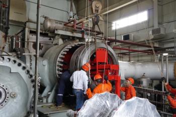
14 MW Atlas Copco expander turbine generator in an ORC plant.[/caption]
Regasification processes
At most LNG import terminals, atmospheric pressure LNG is converted from a minus 260°F liquid to gas at pipeline pressure by first pumping cold LNG to high pressure. The cold, high-pressure liquid is then heated in a sea water heat exchanger to produce high-pressure natural gas, which is directed to the receiving pipeline. Most of the time, the available cold in the LNG is wasted by cooling sea water.
A few installations have incorporated processes that can use the cold such as a co-located air liquefaction plant. Other sites have integrated the gasification process with power generation, using some of this resource for gas turbine inlet air cooling in a combined cycle power plant to boost power output.
At a small number of facilities, LNG is pumped 500 to 1000 psi higher than the receiving pipeline pressure. It is heated with both sea water and a high-temperature heat source such as the exhaust from a gas turbine. The high-temperature, high-pressure natural gas stream is then expanded through a radial inflow turbine to produce power. The turbine discharge is directed to the receiving pipeline. This process has been combined with gas turbine inlet air cooling. Various Organic Rankine Cycle (ORC) cycles have been proposed for power generation integration with LNG regasification.
OnPower has devised a more efficient alternative. Its Re-Condensing Power Cycle is as follows: the LNG is pumped to a high pressure, heated and expanded to produce power. The LNG is first pumped to about 1500 to 2000 psi, heated in the vaporizing side of a vaporizing/condensing heat exchanger, superheated with gas turbine exhaust, expanded in a turbine to produce power, and then re-condensed back to LNG at a pressure of about 520 psi and -130°F in the condensing side of the heat exchanger. At that point, the 520 psi/-130°F LNG is pumped 500 to 1000 psi higher than pipeline pressure, heated, and expanded through a second radial inflow turbine to make additional power, with the discharge of the turbine directed to the pipeline. The cold in the -130°F stream can be used to make additional power via ORC. Residual cold from the ORC can also be used for gas turbine inlet air cooling. The radial inflow turbines involved in these processes can be combined on a single gearbox driving a single generator (See sidebar for a detailed explanation).
The results from this cycle are as follows; The fuel rate falls to between 4,500 to 5,500 BTU/KW-HR depending on the size and characteristics of the gas turbine, system design and other parameters; the power per mass of gasified LNG is more than 1000 kW per Kg/sec; sea cooling is reduced by up to 90%; as no steam is involved, there are no associated problems related to water treatment, corrosion or vacuum leaks; and the equipment has a smaller footprint compared to an equivalent combined cycle plant.
In addition to LNG import terminals, the system can be installed at large peak shaving LNG plants. Most of such plants operate for only a few hundred hours per year. When combined with the Re-Condensing Power Cycle, however, they can perhaps be utilized for thousands of hours per year. To do so, they would store gas as LNG at night using off-peak power and return it to the pipeline during the day while producing on-peak electric power.
In the Northeastern U.S., environmental concerns have restricted the building of sufficient pipelines to satisfy gas demand. A large peak-shaving LNG plant could reduce the need for new pipelines while providing peaking power.
Over-supply of natural gas makes it likely that natural gas and LNG prices will remain low for some time to come. This presents another potential application. LNG export terminals located in areas of high peak electric rates, using a portion of the produced LNG, could cheaply produce on-peak power as a revenue stream.
While this is a new process, the turbomachinery, heat exchangers and cryogenic pumps are well within proven manufacturing capabilities. Primary heat would typically come from gas turbine exhaust. However, it could also come from a gas engine. If ORC is added to the cycle, it can be sized to allow a second identical gas turbine to supply exhaust heat. Alternatively, the exhaust flow from a single gas turbine could be split between the LNG power cycle and ORC. There would be enough residual cold from the ORC to chill the inlet air of the gas turbine(s). Adding ORC to the Re-Condensing Power Cycle almost doubles power output with a nominal impact on fuel rate.
Two different temperature heat sources can be harnessed as part of this cycle such as the exhaust of a gas engine, and the jacket cooling water/turbocharger intercooler heat. With an intercooled gas turbine such as the GE LMS100, it is possible to use the exhaust heat and the compressor intercooling heat of the turbine.
How the re-condensing cycle works:
• Atmospheric pressure LNG in reservoir 95 is pumped to about 1500 to 2000 PSI in pump 90
• The LNG is gasified in vaporizing/condensing heat exchanger 10, then heated in heat exchangers 20, 30, 50, and 40 to about 550°F.
• The heated high pressure gas produces power in turbine 65 as the fluid expands to a pressure of about 530 psi.
• The gas then flows through recuperator heat exchangers 50 and 60, returning heat to the cycle.
• The gas is directed to the condensing side of vaporizing/condensing heat exchanger 10 and re-condensed to an intermediate pressure LNG stream (about 520 psia/-130°F) against the cold upcoming high pressure LNG stream.
• The intermediate pressure LNG is pumped to 1500 to 2000 psi in pump 96 and heated and gasified in ORC condenser 70 and recuperator 60.
• The heated gasified stream is directed to turbine 66 where power is generated as the gas expands down to the receiving gas pipeline pressure.[/caption]
Energy storage
Sites with cheap off-peak electric power could utilize hot heat transfer fluid heated as the second heat source using electrical resistance heaters. Power could be stored for use at peak times.
Another potential storage opportunity concerns the use of liquid air as the initial cold liquid as part of a liquid air energy storage system. In this application, the second pumped, heated and gasified liquid air stream is expanded through a turbine all the way down to atmospheric pressure. Alternatively, a portion of the heated and gasified air can be directed to a gas turbine combustor to substantially increase the gas turbine power. The remaining portion can be expanded through a turbine to atmospheric pressure.
The following manufacturers are thanked for their support with equipment selections and performance data: Chart Industries (cryogenic heat exchangers), Atlas Copco Gas and Process (radial inflow expander turbines); Siemens Energy (gas turbine performance), Tulsa Heaters (gas turbine exhaust gas heat exchangers) and Nikkiso Cryo (cryogenic pumps).
By Jim Berry
Jim Berry is Technical Consultant at OnPower, a packager of turbomachinery, a designer and builder of control panels, and service provider for gas turbine generator sets. In addition to 200 gas turbine generator sets, OnPower’s experience encompasses supercritical CO2, solid oxide fuel cells, gas turbine packages for patrol boats, rocket fin coatings and generator sets to support fracking operations. For more information on OnPower’s patent pending Re-Condensing Power Cycle, visit onpower.com.
Articles in this issue
almost 6 years ago
New research prompts reassessment of offshore filtration selectionabout 6 years ago
Who is in control?Advertisement
Related Content
Advertisement


Advertisement
Advertisement
Trending on Turbomachinery Magazine
1
Baker Hughes IET Backlog Hits Record $37.1B on LNG and Power Generation Surge
2
Simplify, Focus, Execute: The Logic Behind EthosEnergy's Portfolio Reshuffle
3
A Closed-Loop Approach to Turbomachinery Asset Management
4
GE Vernova to Replant First Two Units at Europe's Largest Pumped Storage Plant
5