SUPERCRITICAL CO2 BRAYTON CYCLE
S-CO2 REPRESENTS AN ADVANCE IN POWER CONVERSION TECHNOLOGY
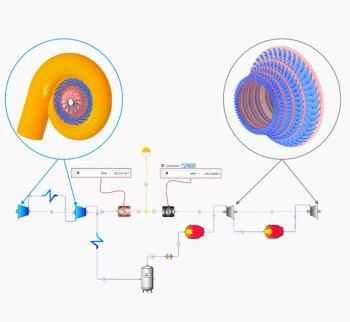
The supercritical CO2 (S-CO2) Brayton cycle is the most promising of the power conversion cycles currently under development. Similar in configuration to an ideal gas closedloop Brayton system, it can suit both bulk thermal and the latest generation of nuclear reactors. The simplest recuperated closed system consists of a heat source, heat exchanger, turbine and generator, a recuperating heat exchanger, a waste heat removal heat exchanger and a compressor (Figure 1).
Numerous studies have been conducted over the last decade on S-CO2 cycle optimization for different applications and for overcoming the challenges in using supercritical CO2 as a working fluid. The biggest advantage of S-CO2 is higher cycle efficiency compared with a Helium Brayton system. This is the result of lower compressor work due to the fact that the cold end of the loop operates at temperatures and pressures near the critical point of CO2, which leads to a rapid increases in density and specific heat (Figure 2).
The other feature is the compact size of the turbomachinery which is the result of the high density of the CO2 working fluid. Compressors and turbines with fewer stages may allow lower component cost and a smaller energy conversion system footprint in comparison to steam or ideal gas Brayton systems (Figure 3).
The S-CO2 Brayton cycle also eliminates the need to deal with sodium-water reactions in the licensing and safety evaluation which makes them more attractive than superheated and supercritical steam cycles. And the temperature profile in the supercritical region can provide a better match to the heat source temperature glide, avoiding so-called “pinching.” In comparison to the Organic Rankine Cycle (ORC) for low-grade heat recovery, the advantages of the S-CO2 cycle are stability, environmental impact and cost.
The ideal gas law cannot be applied to the S-CO2 cycle because gas expansion and compression are not ideal. High pressures and high temperatures may also create challenges in components design. And the high power density of S-CO2 requires that turbomachinery components be designed to deal with heavy torque. Further, advanced sealing systems need to be considered for rotating components.
To increase cycle efficiency when operating below the critical point [3], CO2 has to be cooled to around 20°C, which may pose a challenge for cooling system design. Corrosion should also be taken into account for temperatures higher than 500°C. Special measures should be considered, such as fabrication of components from highcost alloys or use of protective coating.
Nuclear application
A simple Brayton cycle scheme for a sodium-cooled fast reactor was analyzed for a 100 MW net electrical output. The core temperature was higher than 500°C, but because of temperature losses in the intermediate contour, the heat exchanger outlet temperature was set as 480°C. The overall scheme parameters are:
Electrical power production 100 MW
Thermal efficiency 31.54%
Temperature at turbine inlet 480°C
Note that S-CO2 cycle efficiency is sensitive to operating conditions at the bottom of the cycle. That is why the influence of the minimum cycle pressure and temperature on cycle efficiency was studied (Figure 4).
The results demonstrate that when supercritical pressure is maintained, cycle thermal efficiency benefits from cooling CO2 below its critical temperature. But in this case, the turbine will have to operate with liquid and vaporized CO2 which may raise some difficulties from an aerodynamic and corrosion resistance point of view. Cooling CO2 lower than the critical temperature necessitates the creation of an additional circuit as the usual heat sink temperature is around 20°C, which will raise the capital cost of the power plant.
Based on calculated cycle design point results, turbine and compressor preliminary designs were created and the main parameters were defined, such as, axial length, hub and shroud diameters, number of stages and number of blades. Boundary conditions for the compressor are:
Inlet total temperature – 310 K
Inlet total pressure – 7.5 MPa
Outlet total pressure – 21 MPa
Mass flow rate – 1,310.6 kg/s
Rotational speed – 3,600 rpm
During the design process a study was also conducted on the influence of rotational speed on efficiency. The compressor is supposed to be designed for 3,600 rpm in the usual power plant layout. As one can see from the chart the efficiency of the compressor for 3,600 rpm is 85%. But, if a different rotational speed is considered, cycle efficiency can be improved (Figure 5).
For example, the efficiency of the compressor is 89.6% for 6,000 rpm (the cycle efficiency also increases by 0.77% and produced electrical power rises by 2.9 MW). Further, the overall dimensions of this compressor would be much smaller. But in this case it would raise the necessity for a reduction gear. Therefore, this option needs to be considered from a cost-efficiency point of view.
For turbine design, both axial and radial configurations were considered, each designed as follows:
Inlet total temperature – 753 K
Inlet total pressure – 21 MPa
Outlet total pressure – 7.5 MPa
Mass flow rate – 1,310.6 kg/s
Rotational speed – 3,600 rpm
The impact of various stages was considered for an axial turbine.
After five stages, an efficiency gain of 0.1% to 0.2% proved not to be cost effective (after nine stages, efficiency begins to decrease). The selected variant of axial turbine total-to-static efficiency was 94%. While modeling of the radial turbine showed lower efficiency (85%) and twice the dimension, it turned out to be preferable from a manufacturing point of view. But it is important to consider the influence of rotational speed on radial turbine efficiency. The efficiency of a radial turbine may be improved to 92%, for example, by raising rotational speed to 6,000 rpm. This option may lower manufacturing costs by using a radial turbine instead of axial, without significant cycle efficiency loss.
Steam turbines and S-CO2 turbines have different structural load patterns. The average power per stage is 6.5 MW for a steam turbine and 31 MW for an S-CO2 turbine. This mean that for blades with the same D/l the torque is 4.77 times greater. And if the blades of the SCO2 turbine are intended to be full strength, the chords should be doubled in dimension for the same profile.
Development prospects
Most studies have concentrated on overall cycle design and optimization. The next stage will be concentrated on component detail. The obstacles that may appear at this stage include the structural limitations of material, control of cycle operation, corrosion and power plant overall layout. Further development of the S-CO2 cycle will be continued as it is one of the most promising power conversion technologies for next-generation nuclear reactors.
Bibliography
[1] Dostal, V., “A Supercritical Carbon Dioxide Cycle for Next Generation Nuclear Reactors,” Dissertation, Massachusetts Institute of Technology, Department of Nuclear Engineering, January 2004.
[2] Boyko A. V., Govorushchenko Y.N., 1989, Theoretical Basis of Axial-Flow Turbines Optimal Design, Kharkov, Visha Shkola (in russian)
[3] A.Moisseytsev, J.J. Sienicki, 2007, Performance Improvement Options for the Supercritical Carbon Dioxide Brayton Cycle.
Authors
Oleg Guriev is a turbomachinery aerodynamic engineer at SoftInWay with over five years experience in the design of axial and radial turbomachinery.
Yuriy Govoruschenko is chief scientist at SoftInWay with over 30 years experience in developing turbomachinery design systems, optimization and calculation methods.
Leonid Moroz is founder & CEO of SoftInWay, with over 30 years experience in turbomachinery designing flow path for gas and steam turbines.
SoftInWay Inc. is a global engineering company specializing in developing efficient turbomachinery using its flagship software, AxStream for flow path design, redesign, analysis, and optimization, as well as consulting services and educational courses.
Newsletter
Power your knowledge with the latest in turbine technology, engineering advances, and energy solutions—subscribe to Turbomachinery International today.


