
|Articles|March 7, 2020
Testing, inspection and commissioning of gas turbines in oil & gas
Author(s)TMI Staff & Contributors
Advertisement
Gas turbines and their auxiliary systems are subject to individual shop inspection and testing; eventually and before final delivery the full package should preferably be subject to a complete unit test where all job auxiliaries could be tested together for integrated functionality with the gas turbine shaftline running at either full load, partial load or no load. For practicality reasons, some shop auxiliaries might be allowed to be used during the complete unit test; such as fuel gas filters.
This article contains excerpts from the paper, “Gas turbines and associated auxiliary systems in oil and gas applications,” by Emmanuel Bustos, Michael Hotho, Mounir Mossolly and Alfredo Mastropasqua of TechnipFMC Paris presented at the 2017 Turbomachinery Pump and Symposia.
Gas turbines which are newly introduced to the market shall be subject to a qualification process that includes testing which is more extensive and different than the usual shop tests. During the individual testing campaign, some major components of the gas turbine could be verified for mechanical integrity and/ or performance. For instance, the power turbine of an aeroderivative gas turbine will be subject to mechanical run test (MRT) to verify the vibrations levels. While the gas generator would undergo performance test to verify the operating parameters are within the acceptable ranges/ limits.
The performance of the whole gas turbine assembly is performed according to the procedure of the ASME PTC22. On the other hand, all auxiliary systems would be tested at the sub-suppliers’ shops for full functionality. For the complete unit test, the supplier and the contractor/ end-user shall mutually agree on the steps that need to be performed during this integrated test. Depending on the project context and test bed limitations a choice between full load full speed, partial load or no load complete unit test could be made, however it is recommended to always have the shaftline running at full speed.
During the complete unit test (or string test – if not involving off-skid auxiliaries), vibration levels should be measured and verified according to the applicable international codes and standards. The torsional behaviour of the coupled shaftline may be verified during the complete unit test, and the overall noise level of the package should be measured during the complete unit test. In addition, the integrated functionalities and sequences of all the auxiliary systems together is validated.
Guarantees on utility consumptions are checked. Pressure drop in the inlet air system is also checked; similarly, in the exhaust system, both having effects on the gas turbine output power. The ventilation system of the gas turbine is also verified and the pressure inside the enclosure is measured. Finally, the fire and gas system is tested by activating it inside the gas turbine enclosure. The complete unit test could be also an occasion to demonstrate some major mechanical procedures such as the replacement of a gas generator. Although full load complete unit tests are expensive, could cost several millions of euros, and would require few months of preparations; however, complete unit test reduces the execution risks in projects, especially for sites which are offshore and/or at remote location.
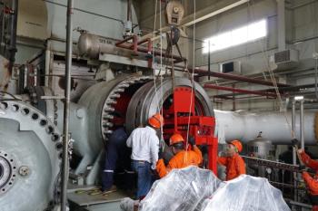
In offshore applications, gas turbine drivers may be mounted on a common 3-point mount skid with the driven equipment. In some cases, the 3-points mounting might create a heavy point load on the structure, mandating a strong structural beam to accommodate the load and precise shimming preparations then need to be done accordingly.
For the 3-points mount installations, shimming under each point should be done based on the reference level of the complete skid. For floating applications, this can only be performed onshore to ensure that the levelling is not impacted by the sea movement. It is important that the skid remains stress-free during the installation sequence. A full welding on each mounting point can be performed (after the skid has been positioned and levelled within minimal tolerances) according to supplier’s requirements. Flatness & levelness requirements on the interface between the gimbals and structure shall also be respected. Full Non-destructive examination (NDE) will then be applied to control the quality of the weld.
For offshore projects where modular design is implemented, gas turbines main skids shall be provided with jacking pads to lift the skid if necessary during the installation adjustments when the use of the crane with slings crossing the decks above is impossible. Auxiliaries such as ventilation ducts, inlet air filter house inlet air duct and exhaust stack will then have to be erected in a predefined sequence; starting from bottom to top. The expansion joints on all the ducting will allow to have some installation tolerances. Silencers will have to be installed (for example in the exhaust stack) as defined by the supplier (sometimes using special guiding tools). To facilitate the build-up/ erection of the ducting, some parts of the ducts will have to be assembled/ connected horizontally at ground and then tilted and lifted for final installation.
In the pre-commissioning phase, all instruments and electrical auxiliaries shall be verified for proper operability. A complete loop check on all instruments mounted in the gas turbine package (including auxiliaries) must be performed. Additional calibration may be needed to confirm the reliability of the instrument. All motors solo runs should be performed (with pump/fan uncoupled) to verify the cable connection and motor rotation. As much as possible, all piping networks around the gas turbine and its auxiliaries should be cleaned. For the oil line, a full oil flushing process must be performed. Lube oil pump of the oil console could be used to perform such flushing. Filters with fine mesh according to gas turbine manufacturer requirements should be installed on the return lines to capture solid particles and other oil contaminants. To perform such oil flushing, gas turbine oil lines are disconnected and bearings are bypassed. Boroscopic inspections for the gas turbine shall also be done at the pre-commissioning phases. A final check shall be done to ensure that the physical equipment is in full compatibility with the engineering documents, such as Piping & Instrumentation Diagram (PID) and hook-up drawings …etc.
Gas turbines are normally commissioned using site fuel gas; unless the gas turbine is dual fuel then commissioning could be done using liquid fuel (ex: diesel). Before starting any test runs of the gas turbine, all the auxiliary systems (including control and power panels) shall be commissioned and proved to be fully functional. Commissioning instructions are always provided by the gas turbine supplier in the commissioning manual, and shall be followed precisely by the commissioning team. Each auxiliary system shall be commissioned by itself. The fire and gas system (F&G) shall be the first system to be commissioned; including the enclosure systems such as fire dampers …etc., to ensure safety throughout the commissioning process. The commissioning of all permissive-to-start shall be then performed.
The sequence of systems that should be commissioned could be: 1. Unit Control and Power Panels; 2. F&G System; 3. Lube Oil Systems (Mineral & Synthetic); 4. Starting System; 5. Enclosure Ventilation System; 6. Fuel Gas System; 7. Inlet Air Filter System; 8. Gas turbine cracking/ motoring system; then; 9. Systems relevant to the driven equipment. Once the gas turbine is in running mode, the first step is to test the emergency trip system: • Test of the emergency push button installed outside the gas turbine enclosure; • Test of the remote trip signal; Vibration control shall be performed to ensure a well stabilization after some running time. When vibration is stabilized within an acceptable range, then the gas turbine is considered ready for start-up.
Advertisement
Related Content
Advertisement

Advertisement
Advertisement
Trending on Turbomachinery Magazine
1
Baker Hughes IET Backlog Hits Record $37.1B on LNG and Power Generation Surge
2
Simplify, Focus, Execute: The Logic Behind EthosEnergy's Portfolio Reshuffle
3
A Closed-Loop Approach to Turbomachinery Asset Management
4
GE Vernova to Replant First Two Units at Europe's Largest Pumped Storage Plant
5