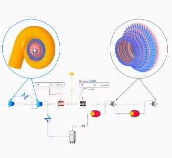
Transonic axial compressors stall
Transonic axial-flow compressors are used to obtain relatively high pressure ratios within a
single stage.
This reduces weight and size and offers a compact design. However, the transonic flow is sensitive to the profile shape and design of rotating and static components. Another important factor is rotor stability when approaching stall conditions.
In recent years, the growth in deployment of transonic axial compressors has been driven by a deep understanding of the aerodynamics and loss mechanisms of supersonic flow, experimental methods and data analysis (such as optical measurement techniques), advances in materials, better blade design and manufacturing, and improvements in casing treatment, air injection and bleeding.
In many axial-flow transonic compressors, the relative flow tip Mach number of the axial rotor is limited to maintain relatively high efficiencies. A typical value for the rotor inlet relative flow at the tip could be a Mach number around “1.25” - “1.35”, depending on design. Today’s high efficiency transonic axial-flow compressors can provide a total pressure ratio in the order of around “1.8”, realized by combining high rotor speeds (tip speed in the order of around 550 m/s) and high stage loadings.
The flow field that develops inside a transonic axial-compressor rotor is extremely complex involving complicated flow features such as shock waves, intense secondary flows, shock/boundary layer interactions, possible development of a blockage, in-corner stall separation, in-upstream wakes destabilization, and other aerodynamic issues which could inducing energy losses, instabilities and efficiency reductions.
Stall at Transonic Axial-Compressors
As the axial compressor moves from the rated operating point to a near-stall operating point, the blade loading increases and the flow structures become stronger and unsteady. The tip leakage vortex can interact with the passage shock wave, leading to a self-sustained flow oscillation in the rotor passage. The results of near-stall operation could be:
·A highly fluctuating fluid flow because of the shock/tip leakage vortex interaction.
·A blade torque variations.
·A shock-induced flow separation on the blade suction surface fluctuates with time.
Above-mentioned aerodynamic effects in a server case even could result in a large blockage effect near the tip. There are two main types of rotating stall in axial compressors:
·The long-length-scale (modal) stall.
·The short-length-scale (spike) stall inception.
The modal stall inception is characterized by the relatively slow growth (over around 15-50 rotor revolutions) of a small disturbance of a long circumferential wavelength into a fully-developed stall cell. The spike stall inception starts with the appearance of a large amplitude short-length-scale (two to three rotor blade passages) disturbance at the rotor tip (so-called “spike”), which grows into a fully developed rotating stall cell within few rotor revolutions.
Transonic Axial-Compressor Design
The airfoil profile, blade thickness variation (thickness distribution), airfoil surface roughness and airfoil/blade detail design have a significant impact on the aerodynamic behavior of transonic axial compressor rotors.
For relative inlet Mach numbers in the order of “1.2” – “1.3” (and even higher), one of the most important factors is to reduce the Mach number in front of the passage shock. The main reasons of the reduction are:
·The strongly rising pressure losses with increasing the pre-shock Mach number.
·The increasing pressure losses because of the shock/boundary layer interaction or shock-induced separation.
The reduction of the pre-shock Mach number can usually be achieved by zero (or even negative) curvature in the frontal part of the blade suction side and by a resulting pre-compression shock system reducing the Mach number upstream of the final strong passage shock. Besides inducing energy losses, the presence of shock waves makes transonic axial compressors particularly sensitive to variations in blade section design.
Small changes in the airfoil shapes and passage areas can significantly affect the performance of transonic blade rows. A small change in cascade throat area, internal contraction, and trailing edge effective camber can affect the aerodynamic of the compressor.
The negative curvature of the blade upstream of the shock led to the reduction of the upstream relative Mach number; for example, from “1.4” to “1.2”. With this curvature change, the velocity slowdown is better implemented. Instead of creating a normal shock, a modern design try to provides two low-intensity shocks. An advanced blade concept (using above mentioned method) can give an efficiency increment of 1.5-2% without changing the choking mass flow. The efficiency improvement is obtained both at the design condition and off-design conditions; it is a bit less on the off-design conditions.
Conclusion
Modern properly-optimized transonic axial compressors can offer a higher performance at a design speed along with a significantly wider operating range; they are capable of maintaining a relatively high efficiency over a relatively wider operating range. For example, there are new designs available which can offer around 2% more efficiency compared to the previous generation designs. In addition, because of a more sophisticated aerodynamics of optimized 3-D shaped components (blades, and rotor assemblies), they can offer a better stall margin.
Author: Amin Almasi is a Chartered Professional Engineer in Australia and U.K. (M.Sc. and B.Sc. in mechanical engineering). He is a senior consultant specializing in rotating equipment, condition monitoring and reliability.
Newsletter
Power your knowledge with the latest in turbine technology, engineering advances, and energy solutions—subscribe to Turbomachinery International today.


