
|Articles|August 1, 2015
Turboexpander Optimization
Author(s)TMI Staff & Contributors
Advertisement
AERODYNAMIC DESIGN SHOULD ADDRESS HIGH EFFICIENCY IN THE EXPECTED OPERATING RANGE FOR HYDROCARBON PROCESSING AND POWER RECOVERY
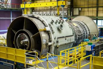
The radial inflow turboexpander or expander is widely used in the hydrocarbon processing industry. The most common applications include natural gas processing for natural gas liquid (NGL) recovery; petrochemical refrigeration in ethylene, propylene, and ammonia production; cryogenic recovery of refinery off-gas; and production of liquefied natural gas (LNG). The expander has also found a good fit in power recovery applications, including Organic Rankine Cycle (ORC) heat-to-power using geothermal heat or industrial waste heat, and in natural gas pressure letdown (Figure 1).
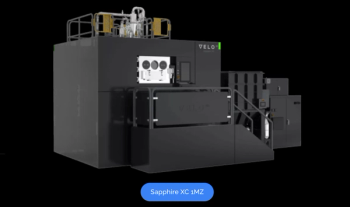
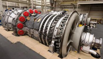
Expanders produce shaft torque and refrigeration from their nearly isentropic expansion of gas, liquid or even supercritical fluid. The torque can be usefully recovered to drive an integral compressor, an external compressor, or an electric generator. The expander inlet fluid must be single phase, but the outlet can be two-phase. As an example, expanders in natural gas processing have been running for more than 20 years that handle condensing vapor with up to 50% liquid by weight at the discharge. By the early 1970’s all new air separation plants were built using centrifugal expander-compressor (EC) units. A modern EC unit is shown in Figure 2.
The expander is equipped with variable inlet guide vanes. The vanes can be actuated externally and used like a control valve to maintain upstream or downstream pressure. EC units are supplied as complete skidded packages including lube oil system, seal gas system, and instrumentation and control systems.
Since the purpose of the expander is to produce refrigeration, it is important for the aerodynamic design to be optimized for high efficiency in the expected operating range. To achieve high expander efficiency, it is important to match the rotor speed and wheel diameter to the isentropic enthalpy drop while matching the blade height and inlet guide vane area to the volume flow. This is accomplished by the OEM expander supplier by using two dimensionless parameters. The first is specific speed, which is defined in Equation 1 below.
The expander OEM does not control Q or H, since these parameters are set by the process design team. The laws of physics determine the optimum value for Specific Speed, and so the only variable remaining for the expander OEM is N, the design speed of the expander. For highest efficiency, N is selected so that the design point value for specific speed should be between 60 and 90.
The second parameter is known as the “tip speed to spouting velocity ratio”: For highest efficiency, the value of U2/Co at design point should be between 0.65 and 0.72 (Figure 3).
Using the speed (N) calculated from the specific speed equation, the expander OEM uses Equation 2 to calculate the optimum expander wheel diameter. Note that a higher value for N at BEP results in a smaller value for D2 at BEP.
The expander efficiency at the BEP is determined from the specific speed relationship. If the value ofU2/Co is in the peak range, then no additional efficiency correction is required. Figure 3 can be used to determine the efficiency multiplier for operation away from optimum U2/Co.
The primary role of the compressor wheel at BEP process conditions is to act as a brake so that the expander wheel will run at its optimum speed N, producing highest efficiency and greatest refrigeration. The secondary role is to efficiently convert the incoming expander power into compressor boost so that the compressor power elsewhere in the process can be reduced.
The process design engineering team determines the compressor inlet flow, and the power coming from the expander determines the compressor input head. The compressor stage efficiency determines the pressure rise that can be achieved from the input head.
As mentioned earlier, the process design engineering team determines the values of H and Q for the expander. Expander efficiency at off-design values of H can be calculated using the U2/Co relationship. For off-design values of Q, the specific speed relationship is not used. Instead, the flow correction factor is determined by a different relationship. The parameter used in the second off-design correction factor is a flow coefficient related to Q/N. This parameter is equal to the ratio of Q/N for the off-design operating case divided by Q/N for the BEP.
Off-design expander efficiency is thus found by multiplying the BEP efficiency (found by using the specific speed relationship) by the primary correction factor above and also by the secondary correction factor (using the Q/N relationship). But how does one determine the off-design speed (N)?
Recall that the compressor design was selected so that it absorbed the expander power at the expander BEP speed, ensuring that the expander achieved its highest efficiency and greatest refrigeration. At offdesign process conditions, the compressor still performs the role of brake device, so at any given set of expander and compressor process conditions the speed is determined by the power balance between the expander wheel and compressor wheel.
Compressor performance for a given design is graphically shown using a compressor map, familiar to all centrifugal compressor users. Compressor power is a function of flow, head rise, efficiency, and speed. Flow comes from the process design engineering team, while head and efficiency come from the compressor map and depend on flow and speed.
This interrelationship must be solved iteratively by: Estimating the off-design speed; calculating the expander efficiency and power using the efficiency corrections described earlier; calculating the compressor efficiency and power using the compressor map; and finally, if the expander power and compressor power match, then the off-design speed estimate was correct; if the expander power is greater than the compressor power, then guess a higher speed and repeat steps 2, 3, and 4. If the expander power is less than the compressor power, then guess a lower speed and repeat steps 2, 3, and 4.
This process naturally lends itself to a computer. Ideally, the expander and compressor performance equations can be incorporated into a process simulation software package so that the EC offdesign performance can be calculated at the same time as the entire plant performance is calculated.
The two expander off-design parameters Q/N and U2/Co can be combined into shown in Figure 4.
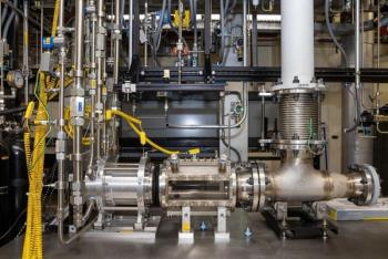
Since the optimum expander speed is usually well above electric generator speed, a gearbox is used for power recovery applications. For the past twenty years, the most common configuration uses an integrally geared solution, where the expander stage is mounted directly on the gearbox pinion shaft, eliminating the need for a high speed coupling and for separate expander bearings (Figure 5).
Shaft sealing can include labyrinth seals, oil film seals or dry gas mechanical seals. For higher pressure drops, the gearbox can be configured with two or more pinions, so that each expander wheel can run at its optimum speed. For higher flow rates, the gearbox can be configured with two pinions each having identical expanders piped in parallel, allowing the use of a single electric generator. Geothermal expanders producing 27,000 kW (36,000 HP) of electric power in a single power train are in service.
The ORC is used in converting heat to electric power when the heat source temperatures are too low for steam, or whenever installing and operating steam boilers is undesirable. The most common uses are in low temperature geothermal resources, where the hydrothermal water is used to boil a working fluid such as butane, propane, pentane, or R-134a in a closed cycle. An installed unit rated for 14.5 MW is shown in Figure 1.
Another use of expanders in an ORC cycle is in pipeline compressor stations, where the gas turbine waste heat exhaust is used to boil the ORC working fluid. Aluminum impellers are not used at the higher operating temperatures seen in these applications. Instead, titanium alloy or 17- 4PH stainless steel are employed.
Natural gas distribution systems use pressure reduction stations whenever a significant pressure change occurs between a higher and lower pressure pipeline. Expanders have been installed in parallel with the existing regulator or control valve in order to produce useful power from this pressure letdown. Figure 6 shows the power available as a function of flow and expansion ratio. It also shows the minimum pre-heat temperature required to avoid possible hydrate formation downstream of the expander discharge.
The modern turboexpander is available in the single-shaft Expander-Compressor configuration (i.e., API 617 expander) from 100 kW up to 23 MW. It is available in the Expander-Gearbox-Generator configuration from 500 kW up to 35 MW.
Expansion ratios as low as 1.05:1 are handled in ammonia plant expanders, as high as 10:1 for natural gas expanders, and as high as 15:1 for pentane or R-134a expanders. Isentropic enthalpy drops as great as 180 Btu/lb (over 400 kJ/kg) have been used for single-stage hydrogen gas expanders. Single impeller exit volume flowrates as high as 70,000 ACFM (120,000 cmh) expanders are available today and larger units are under development.
Written by: Joseph Lillard, Engineering and Marketing Product Manager for Atlas Copco Mafi- Trench Company in the Gas and Process Division of Atlas Copco. For more information: [email protected] OR www.atlascopco-gap.com
Advertisement
Related Content
Advertisement
Advertisement
Advertisement