
|Articles|February 17, 2020
- November/December 2019
Fast start and peak capacity considerations for combined cycle power plants
Author(s)TMI Staff & Contributors
Advertisement
BY JORDAN BARTOL
As renewables such as wind and solar continue to ramp up in the U.S., the need for faster start-capable grid augmentation is on the rise. In the Heat Recovery Steam Generator (HRSG) realm, many new unit construction projects are touting fast-start capabilities. Early-to-mid 2000s combined cycle plants are struggling to stay relevant in an ever-changing market.
A combined cycle plant in California, for example, succumbed to the renewable push by indicating it plans to shutter its doors nearly 20 years prior to its design end-of-life. The closure is a result of legacy technology that made the plant no longer economically viable. What can other mid-life plants do to stay relevant into the 2020s and beyond?
A smart place to begin is with a review of start-up procedures to determine bottlenecks that might exist in the sequence. For one plant, the need for steam turbine seals kept them from bypassing steam to their condenser early on. An earlier source of steam using an existing let down station was identified. This cut about 20 minutes off the start-up timeframe. Another fruitful area to investigate is gas turbine purge time.
In many cases, GT OEMs use a conservative time-frame for their purge requirement prior to light-off of the turbine. Fifteen minutes is a commonly seen number. The National Fire Protection Association (NFPA) Section 85 code requires, “at least five-volume changes at purge rate and for a duration of not less than 5 minutes.” There are also specifics on purge volume requirements and purge rate.
Analysis reveals that OEM time-frames are conservative and can likely be reduced. Several recent projects calculated the required purge time at a range of 5-to-8 minutes for F-Class sized HRSGs. If equipment and control upgrades are in place, it may be possible to eliminate the purge cycle altogether.
To satisfy the purge credit requirements, experience indicates that it is necessary to conduct a detailed review of the plant piping and instrumentation diagram (P&ID) surrounding the gas turbine, duct burner and emissions equipment valving. For most existing plants, this often means retrofitting triple block-and-bleed systems along with controls upgrades which make the purge credit cost-prohibitive unless it is factored in during new unit construction. For plants with Selective Catalytic Reduction (SCR) emissions technology, the ammonia flow control valve can be a start-up hindrance as it correlates to NOx emission block average requirements.
Gas-side temperatures at the inlet to the catalyst may not reach their permissive requirement (typically 480°F for natural gas operation and 550°F for fuel oil operation) until late in the startup due to steam turbine interaction.
For one plant no longer fired on fuel oil, collaboration with the catalyst supplier safely reduced the ammonia flow control valve setpoint from 550°F to 480°F, allowing it to meet emissions block average requirement on a more reliable basis. Additionally, ammonia vaporization on systems with hot gas recirculation (HGR) may become problematic. Find out if the start-up gas temperature at the HGR is hot enough to properly vaporize the ammonia. If not, is it possible to use an upstream (hotter) gas source during start-up to satisfy the vaporization equipment?
Steam drum ramp rate
It is no surprise that the HRSG industry is dealing with more and more fatigue damage in high-pressure steam drums as a result of cycling load profiles and quicker starts. When the rate of pressurization changes quickly, large temperature gradients manifest at the inside/outside drum interface. If the temperature gradient becomes too large, stresses can start cracks at discontinuities like large downcomer and riser nozzles.
When looking at a steam table, a disparagingly large difference in saturation temperature is seen when comparing a cold start with a warm or hot start. For instance, the change in saturation temperature from 0 to 400 psig is about 236°F; from 800 to 1,600 psig is approximately 86°F. What does this mean? There is a larger potential for damage during a cold start compared to a warm or hot start.
Bottom line: Adhere as close as possible to your HRSG OEMs guidelines for cold start-up ramp rates. It is likely that OEM figures for warm and hot starts are conservative. If looking to optimize startups, therefore, consider implementing a system to monitor drum stress by measuring the rate of change of shell and nozzle temperature and using DCS alarms.
Performing a remaining life assessment may also provide valuable information regarding safe ramp rates and amount of weld fatigue life left. Tube metal temperatures continue to rise as gas turbines are upgraded and duct burner systems are pushed to the limit. Practically speaking, the tube metal temperature is a fraction of the steam/water temperature in the tube and the exhaust gas temperature acting on the outside of the tube. This means as gas temperature increases, so does the tube metal temperature. For large units, the first tube module typically experiences its highest metal temperature during start-up or low-load unfired operation.
In HRSGs with duct burner systems, the highest tube metal temperatures in the second module occur while the duct burner is operational (for those with a split superheater (SH) reheater (RH) arrangement. Most creep or overheating failures have been found downstream of the duct burner system. It is likely, then, that more failures are coming down the pike as duct burners continue to fire harder than ever.
One way to visually inspect for evidence of tube metal temperature problems is to look for oxide growth on ferritic pressure parts. Inspect superheater and reheater tubes looking for oxide layer growth. As tube metal temperature increases, so does the rate of oxide growth. Oxide insulates the tube wall, further driving the metal temperature up.
Key point: even a small (nominally 10°F) increase in tube metal temperature (from 1,070 to 1,080°F for Grade 22 steel or from 1,110 to 1,120°F for Grade 91) can reduce creep life by as much as 40%. Nameplate capacity Gas turbine upgrades affect more than just tube metal temperatures. Through analysis, it has been determined that HRSGs often increase steam flow in one or more pressure levels. In one case, a 2% to 5% increase in high-pressure steam f low warranted re-rating the stamped name plate capacity of the HRSG along with pressure safety valve capacities.
Moral of the story: If performing a gas turbine upgrade, do not forget to analyze the effect on downstream HRSG equipment. Questions to ask:
• Is there enough boiler feed pump capacity?
• Will the SH/RH tube/header metal temperatures remain within their design margin?
• Is the steam drum separation equipment still adequate with the additional steam flow?
• Are my safety valves able to relieve properly?
■ Jordan Bartol is Systems Engineer at HRST. Since 1998, HRST has specialized in technical services and product designs for heat recovery steam generators (HRSGs), waste heat boilers, and smaller gas/oil-fired power boilers globally. For more information visit hrstinc.com
Articles in this issue
over 6 years ago
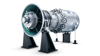
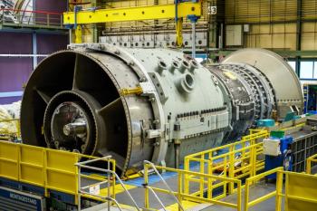
Siemens Gas & Power bets on innovationover 6 years ago
How to use your turboexpanders in energy recoveryover 6 years ago
High-pressure compressors and how to select the right testover 6 years ago
Myth: One machinery solution fits every oil & gas applicationAdvertisement
Related Content
Advertisement

Advertisement
Advertisement