
|Articles|January 7, 2019
Improving accuracy for conversions, modifications and upgrades
Author(s)TMI Staff & Contributors
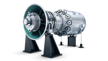
As-built models created by laser scanning are accurate to an eighth of an inch. All the detail around the turbine and compressor can be captured rapidly by correct placement of laser scanners.
Advertisement
By Simon Atkinson
As-built (also known as as-is) data and models, refer to the actual physical sizes, layout and orientation of elements onsite. It is not the orthogonal 2D representation of the original blue print, nor a perfect 3D design model. Instead, it is the imperfect twin of what exists in the real world.
During construction, contractors and engineers modify and correct on the fly to solve problems. The original design drawings and 3D models are rarely updated to reflect these adjustments.
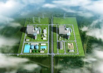
Gas turbine units are never identical, even sister units. It may be a pipe support 6” further down the line, a valve handle rotated to avoid a clash, or a surveyor error in setting out formwork. These subtle differences can cause problems and downtime when the next conversion, modification and upgrade (CM&U) project is underway. Over the life of a facility, these problems are compounded as more projects are executed.
Tape measures
In an effort to operate with accurate as-builts, project managers send out designers and engineers armed with tape measures, plumb bobs, cameras, and note pads to take measurements and evaluate conditions. They crawl into duct work, under turbines, and around skids. However, elements can be missed, numbers transposed, and measurements inaccurately recorded.
Laser scanning is a way to minimize rework due to as-built errors. It is accomplished via a series of 360° × 290° 3D scans that are aligned precisely to generate an accurate and complete digital copy of the real world. This digital copy, accurate to ±1/8", displays each element’s size, location and orientation.
A scanner sends out a light wave and collects what is reflected back as a mass of points. The intricate nature and layout of each GT, the fuel nozzles, combustion cans and manifolds configuration dictate how and where the scanner is placed. Incorrect placement results in partial coverage, shadows (where one object obscures another), and holes. Best practices on how and where to place the scanner and reference targets have been developed over time.
The scanners used in power stations, oil & gas plants, and petrochemical facilities are eye-safe and conform to the same safety protocol standards as a cellphone or regular digital camera. They do not generate heat, trip sensors, or interfere with electrical equipment. Their range is over 185 meters.
Two surveyors can generally capture all the essential details of the enclosure, gas fuel module, water treatment skid, accessory compartment, air inlet, exhaust and all related structural, piping, and other equipment within a 10,000 ft2 area in less than two days.
This first stage deliverable is a collection of 2D views known as a Visual Database. The database is like a digital site-walk and allows the design team to investigate the project area, take measurements and check dimensions on their computers.
This data is then used to generate a replica 3D as-built model, commonly known as a digital twin. It can be delivered in any mainstream 3D CAD format, including AutoCAD, Microstation. Creo 3.0, AVEVA E3D, Catia, and NX. It takes roughly 10-to-14 days to generate.
Caption: Laser scan of the inside of an inlet duct
Best practices
For best results when laser scanning a gas turbine CM&U project, certain key points should be addressed. There are many different laser-scanner makes and models available, but not all are suitable for collecting the necessary data on a gas turbine measurement project.
The size and weight of the scanner, the range, resolution, filtering and point integration into a desired 3rd party software, are all factors to consider.
Prepare the area by making it as clean as possible. Remove clutter such as pallets, boxes, mobile equipment, trash, and scaffolding. Ideally, personnel and forklift traffic should be minimized during scanning as they appear as streaks and ghosts.
As the laser works on a line of sight, lagging from flanges and connections should be removed to provide a more detailed and accurate data set. Scanning is best done with an engineer on site who knows the project and can identify critical elements.
In a power station and around a CCGT where everything is gray, lagged pipes, steel columns on concrete footings, the use of color is redundant. Gray scale scans are faster to capture, file sizes are smaller, and there are fewer files to manage and archive.
As a result, gray scale scanning is preferred by most design teams as it offers more contrast and delivers crisper detail. It can be undertaken in darkness while still producing photo-quality resolution, as it does not rely on any external lighting. Color scanning may offer a more realistic feel, but requires additional photography, consistent lighting, takes much longer, and is more expensive.
Benefits
The approximate cost for a two-day laser scan project is equivalent to the traditional method of sending a larger team armed with tape measures and notepads.
The difference, however, is that laser scanning covers a much larger area, is more complete, and is far more accurate. A Six Sigma study carried out by DuPont concluded that laser scanning should be used on every revamp and retrofit project regardless of size.
Author: Simon Atkinson is CEO of Texas Surveys, a power & process laser scanning and 3D as-built modeling specialist. For more information visit Texas-Surveys.com
Advertisement
Related Content
Advertisement


Advertisement
Advertisement