
|Articles|December 21, 2020
- November/December 2020
Solving the challenge of lean hydrogen premix combustion with highly reactive fuels
Author(s)Jeffrey Goldmeer
The power generation industry is in transition with increasing momentum to reduce carbon emissions. Each year more renewable-based power is generated, changing the traditional electrical grid model. However, the grid still requires firming with dispatchable assets. In the future, these assets may need to have reduced or zero carbon emissions.
Advertisement
Transforming gas turbines into low or zero-carbon emitting systems can be done through pre- or post-combustion options. Pre-combustion choices include the use of hydrogen, renewable or synthetic methane, or biofuels. Post-combustions options include carbon capture and oxy-fuels. As hydrogen is both a fuel and an energy carrier, it is being viewed as a potential critical element for decarbonization of many sectors, including power generation.
Fuels containing hydrogen have been used extensively in the power generation industry for decades. However, there are multiple challenges due to differences in fundamental characteristics (Table 1). Hydrogen has a higher flame temperature than methane, which may lead to increased NOx production. Hydrogen’s lower heating value (on a volumetric basis) is 1/3 the value of natural gas, requiring fuel accessory systems that can accommodate the increased volumetric flow. Increased reactivity is another challenge. Figure 1 shows relative reactivity as a function of inverse blow-off time, which is taken to be a characteristic chemical reaction time. This is plotted against the modified wobbe index. From this graph, it is seen that high hydrogen fuels have a relative reactivity that is ~100x faster than natural gas fuels.
Greater reactivity leads to increased flame speed (defined as the velocity a flame will propagate upstream into unburned fuel). Hydrogen’s flame speed is an order of magnitude faster than methane (Figure 2).
Even blends of hydrogen and natural gas will exhibit increased flame speed; a 50% blend of hydrogen and natural gas has a flame speed at least twice that of 100% methane. Higher flame speed increases the risk that the flame could propagate upstream into the premixer. If the flame is able to anchor and stabilize inside the premixer, this is known as flame holding. Both situations can lead to combustion hardware distress and even fuel nozzle damage (Figure 3).
To mitigate some of the challenges of operating with hydrogen and similar low heating value fuels (i.e. syngas, steel mill gases, refinery waste gases, etc.), gas turbines were configured with diffusion flame combustion systems. These combustors had physically different geometries that mitigated the risk of flashback and flame holding. However, these systems operate at combustion conditions that allow near peak-to-peak NOx formation (Chemically, these are stoichiometric reactions where fuel and air are present in balanced chemical proportions; these reactions also have an equivalence ratio of one) (Figure 4). Depending on the fuel and the combustion system, this could result in NOx emissions in the range of 200-600 ppm. A typical mitigation for high NOx emissions is injection of a diluent (water, steam, nitrogen) into the combustor, but this may result in reduced performance.
A path to resolving this challenge is shifting to equivalence ratios less than one; this is where dry low emissions (DLE) and dry low NOx (DLN) combustion systems operate. However, traditional DLE and DLN systems are not used with hydrogen due to concerns of flashback and flame holding.
One solution was to develop a different type of premixed combustion system with modified geometries for swirl-based DLE and DLN systems. An alternative approach to hydrogen combustion that mitigates the risk of flashback is lean direct injection (LDI). As the name implies, LDI-based combustors operate in a fuel lean mode and achieve rapid mixing of fuel and air using hundreds or thousands of small-scale mixers. The scale of these injectors is such that the bulk velocity of the gas exiting the injector is higher than the flame speed of the fuel, reducing the potential of flashback or flame holding. In addition, the diameter of these holes may be smaller than the quench distance of the flame, mitigating the potential risk of flame holding (The quench distance for a flame is the distance between two plates, or the diameter of a tube, that will quench a flame when it attempts to propagate through the geometry. Physically, the walls of the channel or tube wall conduct enough heat away from the flame that it is extinguished locally).
Numerous studies examine LDI variations and configurations, including co-flow mixing, swirl-based mixing, and jet in cross-flow mixing (Figure 5).
All feature a number of small diameter fuel injectors. Due to their scale, they require more intricate methods of delivering fuel and air. The NASA mixer uses a system in which air flows axially into the multi-tube assembly and through the 25 injection elements (Figure 6). The hydrogen flows into a fuel plenum in the assembly, and is injected axially into two locations in each element, creating a jet in cross flow mixing system.
The jet in cross-flow (JICF) is classic fluid mechanics mixing process where a jet is injected nominally perpendicular to a primary flow. In Figure 7, the jet breaks up and starts to mix as it is sheared by the primary flow.
Combining these concepts, a hybrid LDI/JICF combustion system utilizes a very large number of injectors as well as a jet in cross-flow to create a premixing region inside each injector (Figure 8).
In this mixer, air flows through numerous straight tubes in a parallel array with a fuel plenum that surrounds the tubes. Like the NASA mixer, fuel flows into the mixer through a ring manifold on the outer diameter and is injected radially into the air flowing axially through small-diameter holes in the tube walls. The distance from the injection point to the tube exit plane may vary depending on the fuel and engine conditions. As these tubes have small diameters, bulk air velocity may be greater than the flame speed of the fuel to avoid flashback, including velocities greater than the flame speed for fuels with significant hydrogen content. Even though generating these high velocities can impact performance, due to the short axial length of these mixers, they are able to achieve a relatively low pressure drop.
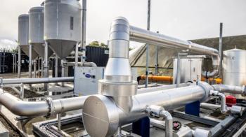
An advantage of the multi-tube mixer that features many small elements is the scalability of the design to any size nozzle or combustor with limited impact on performance. This has allowed initial concept systems to be scaled up to full-scale gas turbine hardware. This has been demonstrated by multiple research organizations and gas turbine manufacturers who developed full-scale prototypes for testing and commercial operation (Figure 9).
GE’s new multi-tube combustion system is known as the DLN 2.6e (Figure 10). Although optimized for operation on natural gas, it still utilizes the LDI/JICF physical geometry and mixing concepts that provided improved operability on hydrogen. Combustion tests demonstrated that this system can operate on blended hydrogen and natural gas with up to 50% (by volume) hydrogen.
Articles in this issue
over 5 years ago
Readying pipeline compressor stations for 100% hydrogenover 5 years ago
The essentials of turbine cleaningover 5 years ago
Q&A with Manabu Saga, President of Mitsubishi Heavy Industriesover 5 years ago
Gas turbine innovation, with or without hydrogenalmost 6 years ago
Can hydrogen revive the fortunes of the turbomachinery industry?Advertisement
Related Content
Advertisement


Advertisement
Advertisement