
|Articles|January 1, 2021
- November/December 2020
The Powerhouse of Industrial Processes: Centrifugal, screw and reciprocating compressors
Advertisement
Fans, blowers, and compressors lie at the heart of air and gas handling applications for many industrial processes. Over time, however, an increasing requirement for depth of focus has evolved for many application engineers while the breadth of experience and vision has diminished. It is crucial to appreciate the range of compression technologies available and balance the demands of performance reliability, operational efficiency, and capital expenditure.
Displacement compression
Positive displacement compression may be considered cyclic. Gas is drawn into an increasing volume of compression chamber before being closed from the inlet. The compression chamber volume is subsequently reduced, thus creating an increase in pressure (and temperature) which can then be “pushed” into the higher pressure outlet system by means of a valve or port as the compression chamber continues to reduce. Closing the outlet and opening the inlet valve or port completes the cycle.
A piston or diaphragm compressor uses the reciprocating linear motion with valves to execute the cycle whilst rotary displacement compressors such as screw and lobe compressors operate using a porting system to sequence the suction and compression cycle.
Figure 2: Twin screw compressor. The slide valve feature present in Howden’s oil-injected screw compressor range gives the added benefit of an energy-efficient method of capacity control.Oil-injected twin screw compressors operate with oil injection into the rotor chamber, which is used for cooling, sealing off the clearance gaps, and lubricating the rotors. The directly driven male rotor, in turn, drives the female rotor using the injected oil as a hydrodynamic film to maintain efficiency and prevent wear. Conversely, oil-free screw twin compressors are designed to operate using a timing gear set up to synchronize the rotors and negate the need for oil injection.
Certain types of gases are not suitable for compression in an oil-injected twin screw compressor, such as polymer-forming or corrosive gases and gases with high particulate contamination levels. The oil injected into the rotor chamber mixes with the gas being compressed. In this case, compression in an oil-free screw compressor is often the best approach, as, in this variant, the gas being compressed is not contaminated with any other medium.
Typically oil-injected twin screw compressors can achieve discharge pressures of up to 75 bar and oil-free range, reaching discharge pressures of up to 45 bar. Capacities up to 74,000 m3/hr and a compression ratio of 15:1 are possible.
Twin screw compressors have the characteristics and stability of a reciprocating compressor and offer the advantages of reduced size, low vibration, and fewer moving parts. This extends operating life and reduces maintenance costs.
Reciprocating piston compressors utilize the linear reciprocating motion of a piston within a cylinder to draw air or gas into an expanding chamber. Reversing direction, the piston then reduces the volume of the chamber to compresses the air or gas to a point where it exceeds the downstream system pressure and is then delivered to the pipework system or storage. Spring-loaded plate valves operate as non-return valves for suction and discharge, being fitted close to the cylinder head or cylinder wall to minimize clearance volume and increase volumetric efficiency (Figure 3).
Typically an electric motor or driver provides power and rotary motion to the crankshaft of a compressor, which is then transferred into linear motion by a connecting rod. For an air compressor, the connecting rod is coupled directly to the piston providing a single compression effect with suction and discharge plate valves mounted within the cylinder head.
A more complex arrangement for reciprocating gas compressors is required where a crosshead and guide is connected to the connecting rod and used to create linear motion. A piston rod passing through distance pieces and several sealing arrangements joins the piston guide to the piston. The gas is compressed on both sides of the piston and is referred to as double-acting. Dependent upon the application, the piston compressor can be oil lubricated or oil free using PTFE (Polytetrafluoroethylene) or similar piston rings.
Reciprocating compressors are rarely single cylinder and can be arranged in vertical, Vee, W, and horizontal opposed configurations. The more complex gas and higher compression ratio duties tend towards horizontally opposed machines arranged to facilitate free draining of any condensable liquids. These are frequently demanded within the oil and gas industries.
Compression ratios are of the order 4 to 1 per stage. Pulsation dampeners are essential for suction and discharge. Inter-stage cooling and separation of condensate allow reliable compression of gases ranging from atmospheric pressure to 600 Bar and higher. Typical applications include refinery, chemical, petrochemical hydrogen and process gas compression.
Diaphragm compressors are a separate form of a reciprocating compressor. They specialize in the compression of high purity/ultra pure gases, corrosive gases, and extreme pressure applications.
The diaphragm ensures total separation for the gas from any form of lubrication or consumable friction seal. The diaphragm’s reciprocating action is achieved by direct mechanical means or indirect hydraulic pressure applied across the diaphragm’s underside for higher pressure and more complex/hazardous application. Modern materials used in the laminated design of actual diaphragm, have dramatically increased the reliability of these machines and provided early warnings of potential rupture.
Capacities are restrictive with diaphragm compressors, but sealing and purity are assured for pressures up to 3000 Bar and beyond. Typical applications include medical and pharmaceutical gases, specialty gases for semi-conductor production and hydrogen fueling stations.
Dynamic compression
For high workloads, dynamic compression can deal with large volumes and provide the highest efficiencies. Axial and radial/centrifugal design concepts are available. A dynamic compressor works with pressure as the constant. The high-speed rotation of blades or an impeller accelerates the gas velocity to provide kinetic energy or dynamic head, which is transformed into static pressure through a tapered diffuser. The molecular weight of the gas being handled together with external factors (such as temperature and pressure) affects density and performance. For uncontrolled constant speed operation, increased gas density at inlet produces increased pressure rise and mass flow with a corresponding increase in power.
Dynamic compressors have an advantage in term of compression capacity. With noncontact components, performance does not degrade under normal operation. Once placed into service, dynamic compressors can operate continuously for several years.
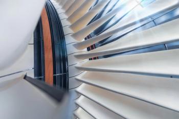
Low-pressure rise single-stage axial fans using blades, for example, are commonly used for building ventilation systems. They are used in applications such as cooling towers, handling high-temperature flue gases, mine shaft ventilation, tunnel ventilation, and aerodynamic wind tunnel testing.
They can become extremely large two-stage units fitted with drivers above 10 MW. Significantly higher pressure rises can be achieved with multistage axial turbine compressors that operate with substantially higher blade tip speeds, more resemblant of an aero jet engine, and equally high cost. Air separation plants and gas-processing plants sometimes make use of these machines.
Low-pressure rise single-stage centrifugal fans, on the other hand, use fabricated impellers to accelerate the gas stream and provide pressure head. Typically, industrial fans operate with tip speeds up 150 m/s, exceeding 200m/s for higher-head applications. Typical applications include industrial handling of air and gas for combustion, processing, and hygiene ventilation.
Demand for increased pressure rise has led to tip speeds increasing beyond 250m/s (can exceed 500m/s given modern materials and design techniques). This is the territory of turbo blowers and compressors where the gas is channeled through the impeller and efficiency gains are obtained by minimizing the gas stream’s turbulance as it passes through the machine at velocities factored in term of mach number. Applications include reactor and furnace/smelter air supply, aeration during wastewater treatment and flocculation of precious metals, sulpuric acid plants and fertilizer production, process gas handling and mechanical vapour recompression (Figure 4).
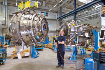
Multistage centrifugal compressors can take the form of single-shaft multi-impeller or integrally geared where reduced diameter impellers and shaft are mounted around a central drive gear. Standard application of multistage centrifugal compressors trend toward process plant air with large bespoke designs for oil and gas processing. ■
By Richard Smith
Richard Smith is Director of Product Strategy at Howden, a provider of air and gas handling compressors for over 160 years. For more information, visit howden.com.
Articles in this issue
over 5 years ago
Readying pipeline compressor stations for 100% hydrogenover 5 years ago
The essentials of turbine cleaningover 5 years ago
Q&A with Manabu Saga, President of Mitsubishi Heavy Industriesover 5 years ago
Gas turbine innovation, with or without hydrogenalmost 6 years ago
Can hydrogen revive the fortunes of the turbomachinery industry?Advertisement
Related Content
Advertisement


Advertisement
Advertisement