TURBO EXPO 2017
SUPERALLOYS, COATINGS, FAILURE ANALYSIS, REPAIR, VANE LIBERATION, FILTRATION, HRSG FOULING AND BLADE CRACKING


Keynote speakers and ASME Gas Turbine executives during the opening address at the 2017 Turbo Expo
The 2017 Turbomachinery Expo in Charlotte, North Carolina, drew more than three thousand people to hear hundreds of presentations from top academics and researchers. Included were plenty of practical sessions relating to a wide range of subjects.
Companies, such as Solar Turbines, GE, Siemens, Man Diesel & Turbo, Southern Company, Exelon, Duke Energy, Liburdi Turbine Services, Gas Turbine Materials Associates, Ron Munson Associates and Natole Enterprises led the way with detailed coverage of operations & maintenance, and developmental issues. Topics of interest included superalloys, high-temperature coatings, gas turbine (GT) failure analysis, repair techniques, compressor vane liberation, inlet air filtration, Heat Recovery Steam Generator (HRSG) fouling, blade cracking and new GT developments.
Dag Calafell, formerly the Chief Machinery Engineer at ExxonMobil (retired) and now a private consultant, kicked off the keynote session, zeroing in on the economic strain facing oil & gas producers, due to lower oil prices. Oil & Gas capital expenditure (CAPEX) was down 40% in 2015 and 2016, he said. Some providers were stringently controlling CAPEX; others were concentrating on operating expenditure (OPEX).
“You can’t optimize CAPEX or OPEX alone; it is necessary to work on both simultaneously,” said Calafell. He examined technologies that would help lower both factors. These typically involved either unmanned, emissions-free or zero-maintenance solutions, as well as Additive Manufacturing (AM, also known as 3D printing).
AM can simplify the manufacturing process, and has the potential to minimize GT emissions and eliminate selective catalytic reduction (SCR) systems. For example, it reduced the number of parts in a new Turboprop engine from 385 to 12. Materials and active surfaces represent another hot zone of innovation, he said. Work is being done in areas such as self-healing thermal barrier coatings (TBCs) and next-generation damage tolerant ceramic metal composites (CMCs). This could reduce hot gas path maintenance. The incorporation of analytics would provide a pathway to real-time optimization. Enhancements to maintenance tools could improve efficiency, said Calafell.
Simulation and modelling, robotics, computer-mediated reality, virtual reality, 3D visualization and operator wear technology could make life easier for those on the plant floor. Such tools may help operators detect problems earlier, take remedial action and improve inspection accuracy.
Next up, Kevin Murray, PMC Engineering and Construction, Duke Energy, outlined his company’s plans. Headquartered in Charlotte, NC, Duke has 7.5 million electricity and 1.6 million gas customers in six states. It owns almost 50 GW of generation capacity. Lower emissions standards and a greater percentage of renewables have greatly influenced Duke’s generation mix, said Murray.
Coal has declined from two thirds to one third of Duke’s portfolio. The slack is being taken up by natural gas and renewables. Duke’s goal: By 2030 reduce CO2 emissions in 2005 by 40%. Duke owns more than 160 GTs. Murray likes their relatively low emissions and their ability to respond to load changes. At the same time, solar power has caught fire.
North Carolina, for example, is the number two state in the U.S. based on the cumulative amount of installed solar capacity (California is number one). In 2017, North Carolina installed 3,287 MW of solar. As 3.25% of the state’s electricity is from solar, this has become a growing challenge to the grid. “We see energy storage and GTs as the solution to renewable intermittency,” said Murray. “We need GTs with fast-start, high-ramp rates and a low turndown.”
Karen Florschuetz, transitioning to a new position in the Siemens Digital Factory division, wrapped up the keynotes. She emphasized drivers for change, such as efficiency, flexibility, digitalization and security. “Half of the Fortune 500 companies from the year 2000 have disappeared,” she said. “They missed the boat on digitalization, which changes everything.”
Florschuetz showcased the 44 MW Siemens SGT-A45 TR. This mobile unit can reach full power in nine minutes, takes two weeks to install, and can be easily shipped. She believes AM and digital engineering are changing established R&D practices. 3D printing enables integrated development, accelerated product iteration cycles, rapid repairs and prototyping, spare parts on demand, and rapid manufacturing, she said. This is being aided by exponential growth in compute power which has advanced the art of simulation and modelling.
Examples of Siemens 3D printing:
• SGT-700 and SGT-800 burner tips: Rapid repair techniques reduced cost by 30% and time by 90%
• SGT-700 and SGT-800 burners: higher performance, and an 85% time reduction
• SGT5-4000F turbine vanes. Development time cut by 75%.
“The digital twin can be designed on a PC, can determine the best flow pathways and the right materials to use, as well as enabling virtual commissioning,’ said Florschuetz. “The future will be digital for the power, and oil & gas sectors.”

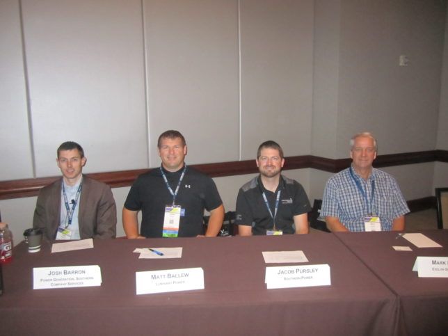
One of the best sessions at Turbo Expo featured a panel from Southern Company, Exelon and other utilities
Utility perspective
By far the best session of the show was, “Combined cycle gas turbine operational risk management: A utility industry perspective.” This session featured gory details of catastrophic failures, extreme blade cracking, HRSG fouling and inlet air filtration.
An analysis of inlet filtration systems came from Josh Barron, a research engineer in the generating fleet research group of Southern Company Research and Development (R&D). “In the past, the approach to filtration has been largely minimalistic,” Barron said, “but as part of a long-term maintenance strategy, the company decided to examine and evaluate filtration.”
Research goals included reducing performance degradation, increasing GT component life, and reducing O&M costs. Southern Company carried out laboratory and field testing of new and used filters. A software tool developed by EPRI evaluated different filter combinations from Clarcor, Pneumafil, AAF, Gore, Camfil-Farr and Koch. In the end, the contract was awarded to AAF for pre-filters, and Gore for final filters and hardware. But Southern Company is not resting on its laurels. It is continuing lab and field testing. When the current filtration contract expires, new filters will have already been evaluated.
Researchers tested filtration efficiency (minimum and average) as well as determined the most penetrating particles. Systems were deployed at five different test sites across Southern Company service territory. These contained a mix of 7FA.03s and MHI501G1s in rural, urban, and industrial areas. “The most telling aspect of GT performance was looking at pre- and post-water wash data to see how well the filter performed,” said Barron. “If water washing improved efficiency, it was clear our filtration approach wasn’t working as well as expected.”
After water washing, the F8 filters showed gains of 2% compressor efficiency and 4% power output recovery on average. E10 filters showed about 1% gain in each category, with E12 went down to half a percent for each. The E12 filters basically needed no water washes yet retained performance, said Barron.
He passed on best practices: Testing should measure resistance to airflow, how the filters are impacted by water, and how results vary across the flow range. This program helped Southern Company reduce offline washing from three times per year to once or twice. By switching some units to HEPA from F8, there was no need to come offline for washing during peak summer months. “We realized several million dollars in savings by deploying better filtration systems,” said Barron. “The payback period is fairly rapid.”
Blade liberation
Another utility plant manager outlined a blade liberation incident at a U.S. plant. It involved S1 compressor blade failures on a GE 7EA GT. The site in question had a humid environment. The blades from the S1 stage of the compressor broke off on a cold February day. The unit locked up quickly.
The trip was initially thought to be due to a loss of flame. Operators tried to restart the machine unsuccessfully. Inspection revealed missing S1 blades, damage to R1 blades and further damage downstream. “One blade liberated and brought with it many other S1 blades that caused damage through the machine,” said the plant manager.
Operators traced the causes to blade fatigue due to high cycle stress, high humidity and corrosion. The formation of corrosion between the vane root and the carbon steel ring caused the vane lockup. This lockup increased the stresses present in the vane during rotating stall. The plant discovered that another utility had encountered the same problem with GE 7EA turbines. The plant manager decided to conduct ping testing on blades at 15 more units, as well as fluorescent penetrant testing. This revealed that 13% of units were at high risk or blade liberation and 20% were at medium risk. “All high- and medium-risk units had their S1 blading changed per OEM recommendation,” said the plant manager. “We also instituted annual testing of each unit.”
A design upgrade from GE no longer uses a carbon steel ring. These new components have been installed on all units. The company maintains readily accessible S1 blading in preparation for any needed blade change outs. As soon as risk levels elevate, blades are changed. Additionally, the company maintains a spare set of S1 blading on site for quick replacement.

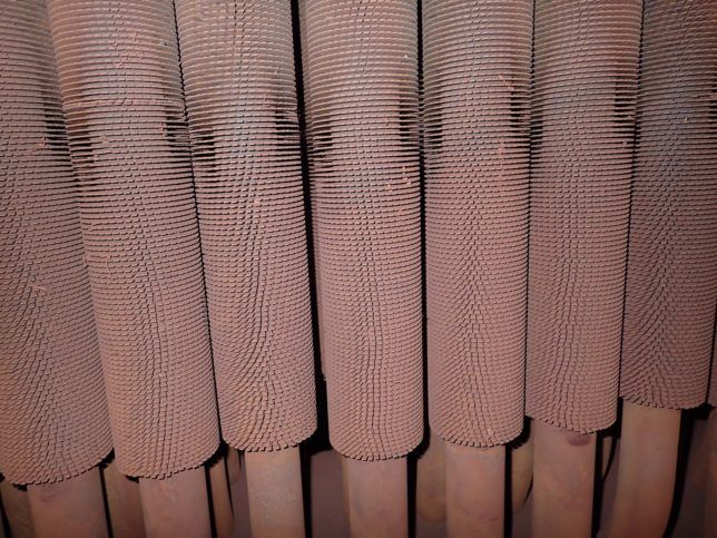
Severe rusting inside an HRSG[/caption]
HRSG rust
Severe rusting of an HRSG became a major challenge for Jacob Pursley, Operations Technician, and HRSG system owner, Southern Power. He noticed back pressure climbing as high as 30 inches in one Nooter Eriksen HRSG, working in conjunction with two GE 7FA GTs and a Toshiba ST. Previous ice blasting of the HRSG showed good results, but areas remained that could not be reached and back pressure continued to climb.
The company decided to try a new technique from GE known as “pressure wave pulse cleaning.” This consisted of controlled explosions throughout the HRSG. One blast took place every two minutes. “After eight blasts, we had almost six inches of debris in some areas,” said Pursley.
Southern Company identified this debris as rust which had probably formed due to a period of high moisture when the unit was offline for an extensive period during an outage. Extreme fouling meant rust flaked off in sheets. This caused increased back pressure as HRSG channels became severely restricted. Plant personnel had to cut access holes into inaccessible HRSG areas. In these regions, the tubes were found to be smooth as opposed to the serrated edges when installed. Technicians managed to blast most sections of the HRSG to get rid of the back-pressure problem.
By the end of the project, 14.5 tons of debris were removed. This brought about a stack temperature decrease of 40°F and a back pressure decrease of 8 inches. The same procedure on a neighboring HRSG produced 24.8 tons of rust, a nine-inch back pressure decease and a 40°F stack temperature decrease.
“High humidity during a fall outage may have accelerated rust accumulation,” said Pursely. “We may have to add dehumidification skids to reduce maintenance costs in the future.”


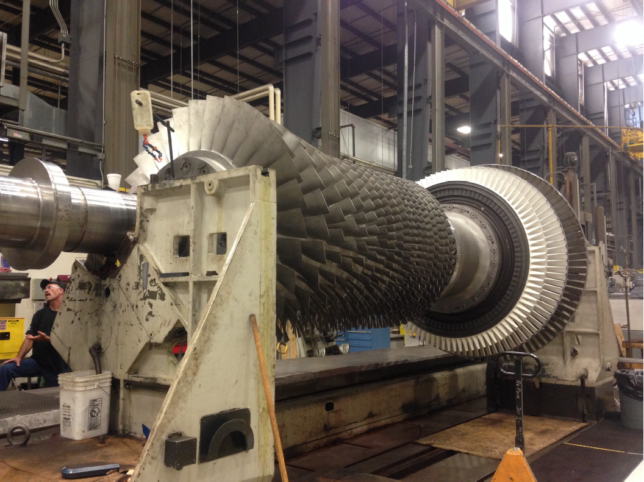
Compressor wheel cracking became a problem at an Exelon plant
Compressor wheel cracking
Mark Lozier from Exelon Generation discussed 7FA compressor wheel dovetail cracking and how to repair it. He said GE had issued a Technical Information Letter (TIL) on this problem. The plant in question had cracking on the last six stages of an 18-stage compressor. This simple cycle peaking unit was situated close to brackish water and used a DLN 2.0 combustor. It had accumulated 1,755 starts and 12,513 operating hours since it began operation in 1995. Repairs and component replacement had been done earlier on compressor wheels 14 to 17.
In 2014, during the replacement of the CDC, due to excess creep and cracks, it was discovered that over 86% of 16th and 17th stage blade dovetail slots were cracked. The company considered blends, weld repair or full replacement of the wheels.
“All options would take too long and would make us miss our summer run where we make most of our revenue,” said Lozier. “We decided to run for the summer and fix it in the fall.”
To minimize risk, the machine only had one start per day and ran for a minimum of four hours. A personnel exclusion zone was implemented when the unit was operating.
Further safeguards included borescope inspections every 25 starts. In total, the turbine ran for 341 hours and 41 starts. It experienced no significant change in crack size during that time. Repair began at the end of summer. The repair plan covered replacing stage 14 to 17 wheels and blades, as well as addressing blade migration and minor foreign object damage in other stages.
Refurbishment or replacement of all hot gas path components was also part of the plan. “We found the 12 and 13 stages were also cracked so we replaced them, too,” said Lozier. “Additionally, we decided to blend and polish the high stress areas on the 10th and 11th stages.”
The company brought in a third party to conduct repairs. This necessitated scanning and making CAD models and FEA models of all parts. This led to a new round bottom design which was found to be superior to the original flat bottom design during analysis and modeling. “The average length of time for cracking to appear was four times longer with the new design,” said Lozier. ‘As of June 1, 2017, we operated 4,046 hours and 362 starts, and the results look good. We used borescopes four times and found no cracking.”
Gas turbine materials
Materials experts presented a tutorial on the application of gas turbine hot section materials for the non-metallurgist. This encompassed basic metallurgy of superalloys, as well as high-temperature coatings used in the hot section, combustors, blades and vanes. Speakers delved into how these materials degrade in service, how they are repaired, and the most appropriate failure analysis methods.
Paul Lowden, Director of Operations, Liburdi Turbine Services, began by discussing the types, metallurgy and mechanical behavior of superalloys used in GTs. Most superalloys consist of crystalline matter which has a grain orientation or lattice structure. Their mechanical properties are largely dependent on this orientation. “Cobalt- and nickel-based superalloys provide a combination of oxidation and temperature resistance, as well as strength, said Lowden. “Techniques for strengthening include precipitation of second phase particles (gamma prime), heat treatment and the formation of convoluted grain boundaries.”
For intermediate temperature, and where very high toughness and fatigue resistance are desired, he said, fine grains are preferred. For example, disks are typically manufactured by forging to form fine-grained microstructures. Blades and airfoils, on the other hand, are general cast. This is because grain boundaries are the weak link in strength under high temperature. Thus, single crystal and directionally solidified techniques have evolved.
“Single crystal is the strongest by far in terms of creep strength,’ said Lowden. “It also has better oxidation and thermal fatigue resistance.”
High temperature coatings
High temperature coatings were summarized by Dr. Henry Bernstein, President, Gas Turbine Materials Associates. He split coatings into two general categories: Environmental and thermal barrier coatings (TBCs). Those used for environmental resistance are typically aluminide internal or overlay coatings.
Aluminides can either be straight aluminides, silicon-modified aluminides or platinum aluminides. They help to form an oxide scale that protects the base metal. This oxide scale is only about 40 microns thick, explained Bernstein, the key to making coatings work. “You want the scale to be continuous and adherent,” he said. “The coating itself is sacrificial, and has to be reapplied from time to time.”
TBCs are different. They add a ceramic layer as an insulator. This lowers the temperature of the base metal to extend component life and durability. TBCs can increase creep life by anywhere from 4 times to 10 or more times. TBCs consist of a ceramic top coat, a bond coat and the base metal. The bond coat forms a thin oxide scale. The ceramic layer is usually Yttria-stabilized Zirconia. It is porous to oxygen.
TBCs are there to guard against attack from high-temperature oxidation and hot corrosion. Hot corrosion is split into two types. High-temperature hot corrosion goes from 1,500°F to 1,800°F; Low-temperature hot corrosion ranges from 1,100°F to 1,500°F.
“Hot corrosion forms a liquid salt on the surface,” said Bernstein. “It attacks the scale and gets into the metal via grain boundaries.” Low-temperature hot corrosion involves sulfur and forms deep pitting. Hot corrosion will take out the coating after 7,000 to 8,000 hours and currently, we have no real solution to that, concluded Bernstein.
Failure analysis
Ronald Munson, President of Ron Munson Associates, examined the intricacies of GT failure analysis. This encompassed the process of failure analysis for gas turbines and their different failure modes. The definition of failure, he said, differs widely. In some cases, it is only regarded as a catastrophic failure of the machine, in others as the inability to perform a specific function with reasonable safety, and at other times it might be defined as a plugged fuel nozzle, a dirty filter or a cracked strut. "Some people class things as failures that others wouldn’t,” said Munson.
There can be, for example, a financial definition for failure. On the other hand, it may simply be a repair cost beyond the planned maintenance budget, an incident that extends downtime or an event that exceeds the insurance deductible. Regardless of the definition, though, it is important to isolate the cause.
Here again, Munson noted that there are various degrees of failure analysis. Level 1 is a determination of what brought about the failure. Level II looks for the cause. Level III involves a search for root causes. Costs escalate as the levels progress. Level II might be anywhere from 3x to 10x the cost of Level 1. Level III, though, may range from 5x to 100x the cost. “Failures almost never have a single cause,” said Munson.
He followed with the steps to take after any kind of failure. The first step is to secure the equipment then document it. This means taking lots of pictures. Ideally, preserve the environment so that analysis can find the reasons behind the failure. Immediate cleaning or transportation of damaged components can inhibit the isolation of root cause. As soon as possible, assemble a root cause analysis team.
Plan the project, assign duties and begin dismantling equipment. “Many dismantle first as they are anxious to get back into production, but that is a mistake," said Munson. Disassembled parts should also be documented before conducting a metallurgical analysis and then drafting findings.
A hot tip from Munson was to not focus so much on metallurgy that you ignore the physics: Hot metal expands, gas flows from high-pressure to low, rotating parts do not like debris, and compressor air gets hot. Further, 99.7% filtration efficiency still leaves 0.3% contamination.
The root cause analysis team should include an owner/operator representative, an OEM engineer, an insurance adjustor, technical third parties and the repair vendor. “If you only have OEM reps on the root cause analysis team, the findings can be too one sided,” said Munson. “What’s not covered under an insurance policy can also influence root cause findings.” If possible, avoid bias which can come from the vendor, the metallurgical or the insurance side.
But there are complications. For example, if a long-term service agreement (LTSA) is in force, as soon as you take the parts out, they become the property of the OEM. Those who favor stress analysis can also introduce bias via finite element analyses that misrepresent conditions. “Be sure to understand the level of failure analysis you really need and try not to allow the results to be filtered through commercial or legal people,” said Munson. “If the data is contradictory to your theory, you either have the wrong theory or the wrong data.”
Repair basics
As time goes on, technology can be forgotten, particularly with legacy equipment. Accordingly, Ronald Natole, President of Natole Enterprises, tackled the different methods and approaches to repairing legacy GT parts. He explained that as many as 5,000 peakers were sold in the U.S. in the ten years following the 1965 New York blackout. Many of these legacy turbines have been performing 10 starts and 200 hours per year. It is common for them to contain their original parts. Components may have been refurbished a couple of times, but they are still the originals. Vendor pitches about hot gas path upgrades often fall on deaf ears. Natole said the amount of runtime does not justify the cost of the upgrade.
As for the best method of repair, he said that recommendations must be based on usage patterns. OEMs may be quick to recommend a major upgrade or the replacement of all blades. But that may not be necessary, or smart economically. There are also other areas to boost GT performance that are much cheaper, such as improving lube oil quality and GT filtration.
Natole pointed out that OEM shops do less than 50% of the overall volume of large frame GT component repair. This amounts to about $500 million per year. Replacement parts add another $4 billion per year to the aftermarket. Yet used or refurbished parts account for only $25 million, and new alternate source parts for $150 million.
Repairs can be minor, medium or major. A major one requires non-standard repair techniques or replacement. “There are things you can see, things you can measure, and things you can’t see such as internal and microstructural faults,” said Natole. “It is important to assess the repairability of a part.”
GT upgrades
Several gas turbine OEMs delivered a session summarizing their latest offerings. John Mason, Director, Gas Turbine Products Engineering, Solar Turbines, provided a rundown of Solar’s ten production GT engines. The company has manufactured more than 15,000 units and has 2.4 billion operating hours in the field. It also offers 18 compressor models with more than 6,300 units shipped. Its products range from 1.2 to 22 MW. A recent aerodynamic upgrade to its Titan 130 raised its mechanical drive capability from 20,500 HP to 22,400 HP, with an equivalent increase to the single-shaft configuration.
“We increased power by 10% without raising the firing temp,” said Mason. “Thermal efficiency also improved.”
Andy Buckenberger, Product Portfolio Manager at Siemens, covered the renaming of the entire Rolls-Royce aeroderivative turbine line to Siemens naming conventions. He said this was required as part of the contractual agreement. The Industrial 501-K, for example, is now the Siemens SGT-AO5 AE “Power customers want fast start, unlimited starts for flexible peaking, high efficiency, fuel flexibility and easy maintenance,” said Buckenberger.
The Siemens SGT-A65 TR is a triple shaft GT with three independent spools running inside each other. It can shift between 3,000 and 3,600 HP without a gear box. All that is required is to change the number of blades in the LP compressor. This changes the speed and frequency. It has a two-stage LP, seven-stage IP and four-stage HP compressor. Siemens has also derived a mobile unit from the SGT-A65 TR. Known as the SGT-A45 TR, it provides 44 MW and has a two-week installation period. It is delivered in three main trailers with some additional shipped elements.
GE highlighted its LM9000 aeroderivative. Dave Wolf, Senior Product Manager, GE Oil & Gas, said it evolved from the GE90-115B jet engine. Specs include 65 MW, 43% single cycle efficiency, and mechanical drive speeds from 2,400 to 3,789 rpm. Maintenance intervals are as follows: Hot section at 36,000 hours; overhaul at 72,000 hours, borescopes every 12,000 hours. The use of a DLE1.5 combustor means emissions levels are 15 ppm NOX and 25 ppm CO. Its four-stage design is said to be suitable for LNG, single cycle, combined cycle and combined heat and power (CHP).
MAN Diesel & Turbo highlighted its MGT6000 series. It has a twin-shaft (MGT6200) and single-shaft version (MGT6100). Output is close to 7 MW. The single-shaft version provides 6,630 MW and 32.2% efficiency. It is mainly being used for CHP.
MAN’s MGT 6000 Series The twin-shaft version provides 6.9 MW and 34% efficiency. Its 11-stage axial compressor comes with variable inlet guide vanes for optimized part load operation. It has six can-type combustion chambers. This three-stage axial flow model can run on gas, liquid and has dual-fuel capability. A purging system for liquid fuel prevents coking of fuel nozzles. It has clocked up over 40,000 operating hours. When used in combined cycle mode, there is a supplementary firing option. CHP plants using this can boost efficiency to 88.2%, said Dr. Robert Krewinkel, MAN’s Head of Team Heat Transfer, Cooling and Secondary Air Systems Gas Turbines.


