TURBOMACHINERY & PUMP SYMPOSIA 2019
NEW PRODUCTS DOMINATE THE SHOW—STEAM TURBINES,
CONDITION MONITORING, BOG COMPRESSORS AND COATINGS
BY DREW ROBB


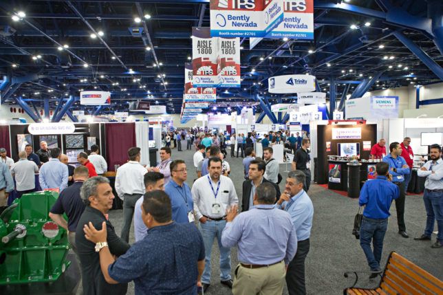
The 48th Turbomachinery and 35th International Pump Users Symposia (TPS 2019) is the premier event for oil & gas-related turbomachinery. Held in Houston, Texas at the George R. Brown Convention Center in September of 2019, it is organized by the Turbomachinery Laboratory at Texas A&M University. The symposia promote professional development, technology transfer, peer networking and information exchange among industry professionals.
This year’s TPS attracted around 4,700 delegates from 45 countries as well as more than 350 exhibiting companies. They were treated to major new product announcements from the likes of Baker Hughes (BHGE) (p. 30), Howden, Atlas Copco and Oerlikon. A rich technical program featured sessions from John Crane, Flowserve, Rotoflow, Solar Turbines, Petrobras and Mitsubishi Compressor. They covered mechanical seals, gas turbine (GT) performance, bearings, GT failures and more.
Steam turbine
It is not every day, or every year, for that matter, that a new steam turbine (ST) is released. Howden chose TPS 2019 to let the world know about its new MONO CBA ST.
“The MONO CBA steam turbine model is an API 611 solution for mechanical drive applications up to 2 MW output range,” said Serkan Nane, Head of Sales, Steam Turbines, Howden.
This ST expands Howden’s portfolio of small industrial STs for mechanical drive applications suited for the refinery and petrochemical industries. API 611 standards (revision 5, 2008) is a mandatory specification for mechanical drives in the petrochemical, refinery and oil & gas markets. To meet this specification, the MONO CBA features a two-stage Curtis rotor, robust construction and operational reliability.
“Our axial Curtis stage shows a significantly higher performance than single- stage technologies at speeds typical in mechanical drive applications,” emphasized Dr. Matthias Schleer, Director of R&D and Technology, Howden. “This is mainly achieved by applying inter-stage guide vanes and a second blade-row. To reduce tip losses, blade tips are covered with titanium shrouds.”
CBA, which stands for Curtis impeller between Bearing Axial flow, is a one-piece bladed design that fits securely on the shaft. This allows the MONO CBA to outperform single-stage technologies while operating at speeds up to 6,000 rpm (up to 9,000 rpm possible). Using elements from Howden’s Kühnle, Kopp & Kausch product brand technology, the new turbine includes a modular design and is available as a bare-shaft assembly or as a full-packaged solution. Journal bearings are installed externally with a protective system. Inlet steam temperature can go as high as 440°C. Dimensions are one meter by one meter by one meter. In the full-package option, the bare shaft turbine is fitted with a gear-and-oil lubrication system according to API 677 and API 614 standards, trip and control valves, as well as turbine control panel and surveillance systems. The turbine can also be equipped with bearing temperature sensors, shaft vibration and position probes.
Coatings
Oerlikon Metco has released a family of coatings designed to reduce hydraulic fracturing downtime by increasing the lifespan and efficiency of centrifugal injection pumps that operate in harsh, demanding environments. Centrifugal injection pumps transport water with entrained sand at high pressure. This generates erosive and abrasive wear throughout the pump.
Pump failure within six months is common. Metco Pump and Metco Sol pump coatings are said to extend mean time between failures by 300% to 700%. Coatings are designed for different pump substrates and operating conditions and applied using robotically controlled systems. The High Velocity Oxy-Fuel (HVOF) application process combusts oxygen and a gaseous or liquid fuel to produce high kinetic energy with controlled heat input. The coating material, in powder form, is uniformly heated by the hot gas stream to a molten or semi-molten condition. The flame and powder are accelerated by a converging/diverging nozzle (air cap) to produce supersonic gas and particle velocities, which propel the powder particles toward the substrate to be coated. The powder particles flatten plastically upon impact with the substrate, cooling and solidifying to form the coating.
High-particle velocities, uniform heating and low dwell time combine to produce coatings that are dense and tightly bonded to the substrate. Coatings have fine, homogeneous microstructures. In the laser-clading process, a laser beam is defocused on the workpiece with a selected spot size. The powder coating material is carried by an inert gas through a powder nozzle into the melt pool. The laser optics and powder nozzle are moved across the workpiece surface to deposit single tracks, complete layers or even high-volume build-ups.
Atlas Copco Gas and Process has also introduced a new approach to cryogenic high-pressure boil off gas (BOG) handling. Drawing from experience manufacturing integrally geared turbocompressors for the LNG market, the company has adapted this technology to handle cryogenic high-pressure BOG processing. This six-stage compressor offers more than 98% reliability and availability combined with significant CAPEX and OPEX savings over conventional technologies. Using cryogenic low-pressure BOG and fuel gas boosting reference machinery,
Atlas Copco Gas and Process has engineered a compressor that handles cryogenic high-pressure BOG applications with greater reliability and efficiency than was previously attainable. This is the first process machine to combine two cryogenic and four warm stages on a single gearbox and skid, allowing for a smaller, more efficient machine. The six stages are said to have the industry’s highest processing capability. The application of dry-gas seals in a cryogenic high-pressure BOG centrifugal compressor is another first for this type of machine. Compared to traditional carbon ring seals, the dry gas seals allow for higher efficiency and lower methane leakage into the environment.


Session tracks
Beyond product announcements and a lively exhibit floor, TPS 2019 featured a technical program with a wealth of short courses, lectures, tutorials, case studies and discussion groups led by experts in their fields. Kenichi Nishiyama and Rishav Jane, turbine engineers at Mitsubishi Heavy Industries Compressor (MCO), discussed stress corrosion cracking (SCC) in STs. SCC occurs when a vulnerable material is exposed to a corrosive environment and tensile stresses. Remediation methods included how to reduce working stress, implementation of new materials and the best ways to eliminate corrosion. The authors recommended rotors be examined for signs of SCC damage by Phased Array Ultrasonic Test (PAUT) to mitigate the risk of failure. Residual life estimations were based on guidelines from the Electric Power Research Institute (EPRI).
Rainer Kurz, Manager for Systems Analysis at Solar Turbines, followed with a briefing on the performance of industrial GTs. He said performance characteristics depend on ambient and operating conditions. Site elevation, ambient temperature and relative humidity, the speed of the driven equipment, the fuel and load conditions all have to be considered. Kurz emphasized the need to understand the flow of energy between the various elements of the turbine. He also discussed control concepts, both for single-shaft and twoshaft machines, driving generators, compressors, or pumps.
“GTs are efficient, have attractive operating and fuel costs and their maintenance requirements are low,” said Kurz. “Their power density offers a lot of horsepower per given amount of weight.” He detailed the differences between single-shaft and two-shaft machines. A two-shaft design has a free power turbine. This enables the operator to change the speed of the driven equipment independently of the gas generator turbine. Single-shaft designs are used more for driving generators with constant speed. “Two-shaft equipment can drive generators, pumps or compressors,” said Kurz. “There are exceptions, but single- shaft machines tend to be mainly for driving generators.”
Revamps
James Sorokes, Principal Engineer, Siemens Gas and Power, Oil & Gas covered the revamping, re-rating or upgrading of centrifugal compressors. He considered aerodynamic factors as well as reasons to revamp existing turbomachinery rather than purchasing new equipment. Sorokes explained that a revamp deals with replacing all or some of the compressor internals, which can often be completed in a week or two.
A revamp or rerate typically means a change in process conditions that requires the introduction of new impellers, new diffusers or drive train changes for speed or power. An upgrade is different. It entails no changes to process requirements but an upgrade of the components. Examples include a switch from riveted to welded impellers or moving from machined to cast manufactured parts.
Various geometric constraints must be addressed in a revamp, such as how much axial space is available for the flow path. Nozzle locations, too, may impact placement of internals. Many old machines have cast casings with return bends cast into the casing, which can limit a revamp. Pressure and temperature raised by a revamp could represent an unacceptable risk.
“Will the casing be able to withstand new pressure loads?” asked Sorokes, “It is important to do an FEA analysis of the casing under the new conditions.”
Another caution: Inspect old parts for damage, faults or other signs of compromise. Available space Sometimes everything must fit in available space. He gave examples of putting new bends and channels inside the old ones to make it work. “The motivation for a revamp is to re-purpose the equipment you have,” said Sorokes. “This might mean more or less flow, higher or lower pressures or reduced power consumption.”
A revamp is likely to cost less than a new equipment order. When considering an existing compressor for alternate operating conditions, you have to evaluate changes to the surge and choke margins, the design point, efficiency and the head coefficient. For example, you might experience a change in the gas conditions that the compressor is handling. If you raise the molecular weight of the gas, the performance maps for the individual stages get narrower. That is, the overall flow range of the stages is reduced. Similarly, if higher speeds are required, the stage maps become narrower.
Those carrying out a revamp should also determine whether to increase or decrease the capacity, and whether to introduce state-of-the art blading or make changes to diffusers. Each decision can affect performance. “Be careful when increasing capacity or the number of stages,” said Sorokes. “When upgrading impellers, consider blade thickness, blade accuracy and different shapes to improve efficiency.”
Many revamps, he said, achieve superior mechanical integrity by moving from a riveted to a welded design. Natural frequencies, too, can change when new impellers or blades are implemented. Installing inlet guide vanes (IGVs) in old machines may be a quick way to revamp a compressor. IGVs add tangential velocity to the flow entering the impeller. You can achieve a capacity increase or decrease by adjusting the guide vanes without altering the rotor. This is far less costly than changing impellers. But there are limitations to this approach as it can reduce efficiency or increase the amount of horsepower consumed by the compressor.
“Diffusers are often the key to the success of a revamp but watch out for impeller/diffuser misalignment or obstruction of the flow exiting the impeller,” said Sorokes. “This can create unbalanced forces on the rotor and lead to sub-synchronous radial vibration.” He offered advice concerning nozzles, inlets, volutes, sidestreams and balance pistons. An undersized volute, for example, can be detrimental to the overall flow range of the compressor. The end user and the company performing the revamp must understand the schedule, the extent of the changes being made and agree on what defines success at the end of the revamp effort.
Mechanical seals
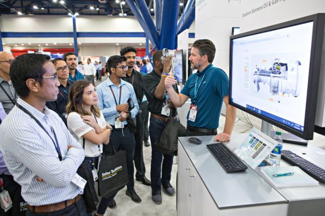
Variable speed pumps are being used more frequently to improve the efficiency and operational flexibility of centrifugal pumps, said Flowserve’s Michael Huebner. Operating these pumps over a range of speeds The exhibit floor features separate sections for pumps and turbomachinery can allow the end user to tailor the pump output in real time to meet the changing process demands. But mechanical seals are often overlooked, or they are only evaluated at the highest operating speed.
The range of operating conditions, he said, can impact seal performance as well as the requirements of the mechanical seal piping plans. It is important for end users, pump OEMs, and seal OEMs, therefore, to understand how to evaluate the mechanical seals present in variable speed pumps. This should include an evaluation of speed, pressures, temperatures and flow rates through the sealing system. Pump and impeller construction, too, can impact seal operating conditions and performance.
John Crane’s Jack Bagain addressed midstream pipeline applications. He said there are few applications that place a demand on mechanical seals such as those associated with the handling of various fluids through pipelines. These applications typically encompass variable fluid properties as well as fluctuations in pressure, temperature and speed.
The remote nature of installations and limited accessibility, too, must be considered. Bagain outlined a variety of sealing strategies and best practices: The performance of a mechanical seal can be thought of as a compromise between leakage and wear. It is well known that the wear rate (and friction) of a leaky seal can be low. In general, when leakage rates are reduced, wear rates increase. Within this relationship, and using modern designs incorporating high performance material, nearly any level of performance can be obtained through selection of the seal arrangement.
The discussion moved onto sealing materials. The use of carbon graphite at pressures above 1,200 psig requires thorough evaluation. Silicon carbide is hard and wear resistant with good mechanical properties, as well as pressure velocity (PV) characteristics. A silicon carbide/ graphite composite has improved dry-run survivability and thermal shock resistance, as well as exceptional PV. This material is often used when operating pressures might exceed the limits of conventional metal-filled carbon grades. Tungsten carbide is tough with good wear resistance, but its PV is limited, and susceptible to heat checking damage.
Bearings
Centrifugal compressors and steam turbines often use hydrodynamic journal bearings. They can either be fixed-sleeve or the tilting-pad type. While compressor manufactures push design limits to reduce costs and optimize machine performance, this can increase the risk of bearing issues. Unfortunately, industry standards offer limited guidance on how to design or apply hydrodynamic bearings to prevent wear or damage.
“Guidance is needed on how to identify and avoid potential bearing issues with hydrodynamic journal bearings in centrifugal compressors and STs,” said Patrick Smith, Air Products Fellow, in a tutorial co-authored by Robert Benton, Product Development Engineer for Rotoflow, an Air Products Business. “This applies to a new machine or when retrofitting a new bearing into an existing machine.”
“Bearing failures are typically characterized by actual damage, such as babbitt fatigue, but this doesn’t get to the underlying causes in design, bad installation, operation, maintenance or quality,” said Smith.
He cited several API standards as well as an AGMA standard, but cautioned users that the API standards, in particular, do not include much to help the user in evaluating bearings. He cited three failed bearing examples that fell within acceptable limits per the standards in terms of surface speed, unit loading and clearance ratio.
“When reviewing a bearing design for an application, the old method of applying simple limits to journal speed and unit load can be ineffective in preventing bearing issues or result in a more conservative design than is needed,” said Smith. “Criteria to use should include minimum film thickness, bearing temperature, side leakage, oil supply, frictional (power) losses, maximum pad temperature and peak oil film pressure.”
Rotoflow recommended: a calculated minimum oil film thickness of 0.8 mils under all design operating conditions; a maximum measured bearing operating temperature of 212°C in the shop and in the field under all process and oil operating conditions for tilting pad babbitt bearings; condition monitoring to provide early detection of bearing wear or damage; a protection system that includes appropriate protections during transient conditions; and an oil analysis program to detect early signs of oil degradation.

Case studies
Harris Sabri, a Staff Rotating Engineer from Petronas, discussed the impact of harsh environments on GTs in Malaysian offshore waters. The biggest issue, he said, is hot corrosion. From the first failure in 2008, Petronas suffered 12 confirmed hot corrosion incidences across multiple sites. An individual address to each incident proved ineffective. Instead, a fleet-wide approach was instituted.
Sabri defined a harsh environment where alkaline metals combine with sulfur to create a corrosive molten salt in offshore and coastal locations. Contamination may come from air, fuel and water. “Molten sales cause accelerated oxidation or a sulfidation attack on high-temperature alloys,” said Sabri.
He described Type I high temperature hot corrosion (800 to 850°C) as happening typically at the blade tip. Type 2 hot corrosion (670 to 750°C) is generally a pitting attack that occurs under the blade platform.
Type 2 was the issue at Petrobras. Five primary GT models operate in the Petronas fleet of 225 GTs. Model C was the most affected by hot corrosion. Of its 29 units, 16 experienced failures. Among the many other turbine models, only five failures were found. Therefore, investigation focused on Model C. Eight sites had the Model C turbine and only four had failures. Root cause analysis found fouling in the compressor air path. Traces of oxygen, sodium and sulfur were found, as well as clogged air filters, water ingress in the inlet duct, water in the diesel fuel and clogged liquid fuel filters.
Petrobras brought together operators from each affected plant as well as the GT OEM and users from outside Petronas with similar problems. The solution involved upgrading air filtration to prevent corrosive species ingestion from F7/8 filters to E10 hydrophobic filters. Petrobras added G4 pre-filters, too.
“The original filters became clogged at 9,500 hours,” said Sabri. “The new ones were found to be in good condition after 19,500 hours.”
In addition, blade alloys (higher chromium content) and coatings were introduced with better corrosion resistance. Fuel standards were raised to prevent corrosive species ingress from dirty diesel. Digital monitoring was also implemented as a preventive measure. “We have had zero failures since we put in these preventive measures almost two years ago,” said Sabri.
TPS 2020 will be held Sept. 15–17 in Houston with short courses on Sept. 14. For more information visit tps.tamu.edu.


