
|Articles|October 1, 2011
COMPRESSOR MAKERS TARGET OIL & GAS
Author(s)Drew Robb
Advertisement
THE GOAL: MINIMIZE COSTS, INCREASE FLEXIBILITY AND REDUCE MAINTENANCE
Centrifugal compressors are finding greater demand in oil & gas (O&G) applications, particularly as less traditional forms of gas become more commonplace. Companies are replacing screw and reciprocating machines with upgraded centrifugals to move higher flow volumes; improve availability; lower cost; reduce maintenance (Sept/Oct11, p. 18); and handle heavier offshore natural gas blends.
This trend is particularly apparent in coal seam gas or shale gas in countries with large coal and gas reserves such asAustralia, says Ralf Kannefass, Head of Compression & Solutions Turbo Equipment at Siemens.
Indeed, more challenging projects and user demands are driving the introduction of new technology around the world:
• Cameron has introduced sculpted diffuser plates and high-speed pinion-bearings
•Atlas Copco is working on better stage and impeller efficiency
•Dresser-Rand’sDatumD6R6Baddresses high-density gases at high pressures
• Kawasaki Heavy Industries - Kobe (KHI) has adopted vaned diffusers for smalland mid-flow stages
• Rolls-Royce has optimized the aerodynamics of its RCB compressor
• Man Diesel & Turbo touts the advantages of its motor-driven hermetically sealed compressors • Kobelco emphasizes the importance of API 617 compliance
• GE Oil & Gas has geared up for CO2 applications
• Elliott Group has been refining its coatings
• Solar Turbines has introduced the C85 pipeline compressor
Details of these applications and much more are covered below, demonstrating that the compressor field remains a vibrant part of the turbomachinery landscape.
Integrally geared
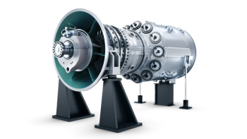
Siemens integrally geared turbocompressor has won the company several high pressure CO2 projects in the U.S. These compressors are used in chemical and petrochemical processes, as well as air separation (Figure 1). New applications that are likely to become of major importance are in the compression of CO2 for carbon sequestration and storage (CSS) as well as enhanced oil recovery (EOR).
Integrally geared compressors are more efficient than axial or in-line centrifugal compressors, says Kannefass. This is because all impellers have an axial flow inlet; an internal gear with a fixed speed drive allowing impellers of different diameter to rotate at their optimum tip speed; and cooling of the air (or CO2) after each compression stage.
Siemens’ STC-GV line of integrally geared compressors covers a flow range, up to 600,000 m3/h. With the increase in impeller diameter, and the volutes assembled on the gear casing, the diameter of the bull gear increases to the point that the tip speed of the teeth exceeds the admitted load of the present material, explains Kannefass. An improvement in materials allows a further increase in capacity.
The recent extension of the STC-GC series covers 120,000-400,000 m3/h capacities with five casing sizes. Pre-engineering of compressor components has reached 80% and the remaining 20% is covered by customized parts.
A compression ratio of 6.5 is achieved in three stages, with an Inlet Guide Vane (IGV) on the first stage inlet for flow control. The number of heat exchangers is cut to seven by combining the interstage and after cooler units. A compressor control system known as Scaut CPD safeguards the compressor against improper operation conditions. 50 Hz models are currently available with 60 Hz versions coming out at the end of the year.
“The main benefit of the integrally geared compressor versus the singleshaft compressor is the higher impeller efficiency with axial flow intake in combination with high head coefficients and the flexibility to adjust the speed for optimum flow coefficients,” says Kannefass. “In addition, the overall number of impellers in a single-shaft compressor is twelve compared to seven on the integrally geared compressors, which is also due to the reduced head coefficients for single-shaft impellers.”
Siemens will supply up to 10 compressor trains to Australia Pacific LNG in Queensland, Australia. Each train consists of two compressor skids, one low pressure and one high pressure, with both skids carrying two compressors with variable speed drives. Each train is designed to transport around 84 MMSCFD (million standard cubic feet per day) of gas.
Sculpted for efficiency
Cameron Process and Compression has been making a series of improvements to its centrifugal compressor line. Aerodynamic components such as impellers and diffuser plates are sculpted for improved efficiency, says Mahesh Joshi, President of Centrifugal Compression at Cameron Process and Compression. The company has the production capability to produce impellers custom designed for unique applications, he adds. “Our 5-axis milling machine cuts impellers from a solid forging to application-specific height, blade angle and hub profile.”
The sculpted diffuser plates are designed to direct compressed air or gas leaving the impeller to the next compression stage. This exit air is guided through the narrow pas-sages formed by the diffuser to increase pressure (Figure 2).
Enhanced rotor dynamic modeling techniques have enabled high-speed pinion-bearing designs to become a reality. As a result, engineers can better predict the stability of the rotor-bearing systems at the product design review stage. This has led to the design ofmachines that operate at conditions well separated from the lateral and torsional critical speeds of the rotor-bearing system.
A variety of sealing solutions have also been developed based on applications that range from simple labyrinth to dry face gas seals. “For process gas applications, we have built machines with the following types of gas seals – single, tandem, multiport babbitted and ring seals. We have been able to achieve sealing for a wide range of gas molecular weights, from as low as ~6 to ~44,” says Joshi (Figure 3).
Further, the company has released variable speed drives for process gas applications, and the latest version of its Maestro software. The Maestro Universal Controller provides compressor capacity and anti-surge control, information management tools and network connectivity on a Windows platform. The Maestro SystemiserNX manages multiple compressors with legacy control systems. It can link up 16 compressors.
Bigger, faster machines
In addition to machine size, achieving higher pressures is another growing customer need, especially in CO2 applications. To meet this demand, Atlas Copco Gas and Process is working towards range extensions of its existing product offerings.
“We are seeing a continued customer demand for bigger machines, particularly in air separation and for CO2-related applications,” says Peter Wagner, President of Atlas Copco Gas and Process Division. “On the air separation side, there is a continued move toward higher flow volumes.” Further, the company is emphasizing improvements in stage and impeller efficiency, as it relates to highspeed technology.
There is also a rising demand from customers for hermetically sealed, oilfree solutions that are direct-driven and equipped with magnetic bearings, says Wagner. “It’s a technology that eliminates mechanical losses and offers maximum availability.”
GE Oil & Gas is also responding to the renewed interest in pumping CO2 in liquid and supercritical states for EOR and CCS projects. The company has selected the BB5-type multistage barrel pump as the best option for high-pressure CO2 applications. The opposed impeller back-to-back rotor configuration is said to provide excellent overall efficiency compared to an inline rotor configuration. This is because the central balancing bushing has a smaller diameter than a balancing drum, thus reducing internal leakages that become a source of power losses when operating with low viscosity fluids.
Centrifugal technology typically can cover discharge pressures up to 25 MPa (3,600 psi). New API 610/ISO13709 compliant centrifugal pumps, however, have been developed that are capable of providing up to 60MPa (8,700 psi).
Dresser-Rand’s Datum D6R6B addresses a specific niche in dealing with high-density gases at high pressures (Sept/Oct11 p. 39). This centrifugal machine can achieve a discharge pressure exceeding 550 bar (7,975 psi) while compressing gases that are heavier than the usual offshore natural gas blends. This includes a CO2-rich gas blend that is nearly 65% heavier than normal.
The D6R6B will be used on two trains to be installed on a floating production, storage and offloading (FPSO) vessel destined for duty off the coast of Brazil. They will be used to compress a mixture of natural gas and CO2. The compressor was tested at the company’s facility in Olean, NY, at full load and field conditions exceeding 550 bar discharge pressure for a range of gas compositions.
“At these conditions, the unit handles a gas in a super-critical state,” explains Chris Rossi, Dresser-Rand’s Vice President of Technology and Business Development. “The unit achieved a discharge pressure in excess of 560 bar (8,120 psi) compressing the CO2-rich gas while exhibiting stable rotor dynamic behavior, generally considered the greatest challenge in this class of machinery. It reached what we believe to be the highest gas density any multi-stage centrifugal compressor has handled.”
Gas density is a critical parameter affecting compressor stability and reliability. Typically, high pressure causes instability. The back-to-back design of the Datum model is stably dealing with a density level equivalent to what a natural gas compressor would achieve at a discharge pressure of approximately 900 bar (13,000 psi).
While the units will be used in the upstream market, the technology is applicable to other market segments requiring the compression of CO2 and heavy gases, such as urea production and carbon capture and sequestration, adds Rossi.
Evolutionary journey
KHI sees developments in compressor technology as an evolutionary affair. Over the past 20 years, small but steady rises in efficiency have been earned via stationary design and impeller bladeloading design improvements.
The company is making gains in stage efficiency driven by the shift to designing impellers in three dimensions (3D) instead of the traditional 2D for large flow stages, as well as adopting vaned diffusers for smallandmid- flow stages, says Ken Kihara, assis-tant manager for KHI’s Compressor Engineering Section. These designs are verified through computational fluid dynamics (CFD),which has helped designers to isolate small shifts in impeller geometry to optimize blade loading and obtain a wider operating range.A full-stage CFD, which includes not only the impeller, but also the stationary flow passage (impeller cavity, diffuser, return channel, return vane region) is done to verify the overall stage efficiency.
Reducing internal leakage has also been targeted by KHI. Labyrinth seals with slanted teeth, for example, suffer less wear and reduce internal gas circulation (Figure 4).
For EOR as well as FPSOs, the company isworking on a high-pressure, small-flow compressor. High density gas means greater destabilizing forces that can cause excess rotor vibration. Further vibration can result fromthe strong swirl of high-density gases at the shaft seal. To suppress vibration, a largebore ratio rotor, damper seals and other deswirling features provide greater stiffness and damping to obtain rotor stability.
To deal with smaller capacity, the impeller diameter is being reduced, and some impeller exit widths are as narrow as 3mm. To manufacture them accurately, the company has introduced vacuum brazing instead of conventional welding for the hubto- shroud connection to avoid heat deformation. “We are doing single stage testing as well as high-pressure testing at our R&Dtest rig to verify these new design elements,” says Kihara.
The company also has developed an oil-free compressor package equipped with magnetic bearings and a high speed motor. Testing is being conducted with load variation to ensure the system integrity for stable operation at a customer’s site. It is also being optimized for compact and large capacity design in collaboration with the company’s system technology development division.
Cutting turnaround time
One of Rolls-Royce’s contributions is the RCB barrel compressor which has a new family of 33 impellers. “Larger frame sized barrel compressor casings are becoming more of a trend at higher pressures,” says Scott DeWolfe, Product Director for Industrial Compressors at Rolls-Royce.
The spacing between the RCB impellers has been reduced to optimize aerodynamics and accommodate a broader range of flow. Standardized casings and nozzles and improvedmaintainability features are part of this design (Figure 5). The shear ring has been reworked to better transfer load from the cover to the casing. Smaller bolts have been introduced which can be tightened by hand to eliminate the need for hydraulic equipment during removal.
“This model is 2% more efficient than the previous RCB,” saysDeWolfe. “The first production project with the new impeller design is now in progress.”
By removing the coupling spacer, retainers and shear ring and disconnecting the auxiliaries, the internal cartridge assembly can be removed in one piece. This makes it easy to performwork on the stator, rotor, seals and bearings. “Everything comes out together in one subassembly,” adds DeWolfe. “If you have a new one ready, you just slip it in. This cuts down turnaround time for a bundle change-out to 24 hours versus 3 to 4 days or more.”
Horizontally split bearings are included for ease of access. The bearings can be inspected or changed without removing the entire cartridge. These features have also been added to Rolls-Royce’s smaller RBB compressor and are coming soon on the larger RDB models.
DeWolfe touts the benefits of twinning RDB compressors with Trent gas turbines to provide a 50 to 60MWcompression system. This makes it possible to compress gas to 2,500 to 3,000 psi and absorb 50 to 60 MW of power in one compressor casing. In addition, Rolls-Royce has introduced an upgraded RFBB30 pipeline compressor to market. It has 30-inch horizontal nozzle connections, a 222 bar maximum working pressure (with a prototype tested as high as 333 bar), can run at up to 8,000 rpm, up to 88%efficiency and 40+ MW of power capability. The RFBB30 is wellmatched to the RB211-H63 gas turbine, according to DeWolfe.
He points out that several upcoming, large pipeline projects around the world will require pressure levels in the 2,500 to 2,700 psi range. These levels are best suited to drivers in the 40 to 44MWrange.At these pressures, a compressor with a 36- inch flange would be too large. So Rolls-Royce sees its 30-inch flange RFBB30 compressor as the right solutions for such applications.
Automatically Variable IGVs (VGIVs) are available on the RFBB30 (and on other models as well). These are said to be most effective on single-stage pipeline compressors but can be used in applications up to three stages. This allows performance to be adjusted to provide higher or lower flow levels as desired. As well as being included in newmodels, they can also be retrofitted onto older models (Figure 6). “We recently upgraded some pipeline compressors in Canada with VIGVs,” says DeWolfe. “This made the compressors more flexible, efficient and available.”
State-of-the-art coatings
Users seeking anti-fouling protection offered by an amorphous nickel coating benefit from several weeks’ reduction in turnaround, according to William Blair, a Senior Consulting Engineer at Elliott. “Elliott’s PS-523 amorphous nickel coating can be applied to an assembled rotor with carbon steel components.”
Elliott developed ameans ofmasking the rotor tomaintain component gaps after coating. These gaps are required to enable the natural bending of the rotor during operation, which previously demanded a full disassembly of the rotor prior to coating of the components (Figure 7). In addition, the company has been working on the use of magnetic excitation of rotors under shop test conditions. Applying a known magnetic force, says Blair, mitigates uncertainty associated with traditional testing that relies on bulk excitationmodels. “Unique characteristics of rotor behavior can be separatedwith the control offered by magnetic excitation, which enables improvement in the correlation of force and response.”
Solar Turbines, which has 5,300 gas compressors operating globally, manufactures pipeline compressors for natural gas transportation and gas compressors for upstream oil & gas applications. Each line shares design concepts that have been scaled to adapt to different driver sizes and applications (Figure 8).
The most recent developments include a test facility and new compressor. The testing plant, which contains a 20,000 hp driver, means that gas compressors weighing up to 100 tons can be built and undergo ASME PTC 10 Type 1 and Type 2 testing at Solar. The latest compressor model known as the C85 followed the introduction of the 30,000 hp Titan 250 gas turbine, which required a new pipeline compressor. It is an aerodynamic scale of the Solar C65 compressor.
“For production compressors, scaled versions of the C51 compressor have been designed that will cover higher and lower flow applications, as well as higher and lower pressure applications, from gas gathering and boosting to storage, withdrawal and gas lift,” says Rainer Kurz, Manager of Systems Analysis for Solar Turbines. “Additionally, Solar Turbines offers dual compartment machines, and has built compressors which are operating in the field at over 3,000 psi discharge pressure.”
The North Sea continues to challenge compressor OEMs as their customers drill at deeper andmore challenging locations.Man Diesel&Turbo has received an order to supply four compressors thatwill be used on the North Sea floor near Norway at a depth of around 250 meters. These are motor-driven, hermetically sealed compressors scheduled for commissioning in 2014, says Klaus Stahlmann, CEO ofMAN Diesel & Turbo.
Kobelco, too, a supplier of both integrally geared and single-shaft types of centrifugal gas compressors, has targeted that market. Its integrally geared centrifugal compressors include SuperTurbo for process gas services with API 617 and air services with API 672. The company’s single-shaft centrifugal compressors are also API 617 compliant. The application range for these products extends up to 350 barg (5,000 psig) and 400,000 m3/h (235,000 cfm).
Advertisement
Related Content
Advertisement

Advertisement
Advertisement