
|Articles|April 27, 2019
EXTENDING MEAN TIME BETWEEN OVERHAULS
Author(s)Drew Robb
Advertisement
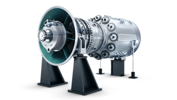
Caption: Normalized 2D metal temperatures used for mechanical integrity and 3D
thermal assessment of the entire power turbine at steady-state, full-load conditions
GAS TURBINES OF ALL KINDS CAN REDUCE DOWNTIME WITH UPGRADES THAT LENGTHEN OVERHAUL INTERVALS
BY GAUTAM CHHIBBER
The oil and gas industry has had to operate for some time in a sustained low-price environment. In light of this, companies throughout the upstream, midstream and downstream sectors have gone to great lengths to reduce the operating and lifecycle costs of assets. A project was launched, for example, to double the mean time between overhaul (MTBO) for an SGT-A35 GT61 aeroderivative gas turbine (GT). This solution incorporates the SGT-A35 (RB211) Gas Engine with RT61 Power Turbine (PT).
Nearly 40% of these units were covered by long-term service agreements with an MTBO of 50,000 hours. The goal of the project was to increase MTBO for the RT61 Power Turbine to 100,000 hours for packages in both power generation and mechanical drive duty. To validate various analytical predictions, test data was recorded from full-load production pass-off tests. Gas turbine air system data, power turbine air temperatures, and metal temperature data were collected from the outside of the casings at design and off-design conditions. Rotating thermocouple measurements from previous development testing were used for disc metal temperatures and thermomechanical analysis validation.
While this article specifically addresses a use case for the SGT-A35 GT61 aeroderivative gas turbine, this solution could be applied to any gas turbine. For light industrial gas turbines, flexible overhaul intervals are available which allow extending the MTBO based on gas turbine loading. For aeroderivative turbines, the potential to extend overhauls based on loading is still in development.
Thermal analysis
Two-dimensional (2D) thermal analysis was carried out to predict the thermal characteristics of turbine casings, vanes, blades, and discs at rated conditions. It included steady-state peak temperature predictions for component creep stress analysis and thermal gradients at various transient steps for disc low cycle fatigue analysis. This was necessary to understand the impact of thermals on extended MTBO life.
3D finite element analysis (FEA) was used to predict accurate thermal characteristics of hot gas path components, hot gas path radial temperature profiles, and cooling flows. Temperature predictions and mechanical displacements were compared with test results before mechanical integrity assessments were conducted. A thermal model was run according to development test cycle engine conditions. Transient metal temperatures at various spatial locations were predicted (Figure). The effects of the radial inlet temperature profile are evident from the contour plot. The same 2D thermo-mechanical model was run at test conditions, and the predictions were compared with the test data.
It is also useful to compare: transient normalized metal temperatures for a standard cycle between actual test; the normalized metal temperature between test and prediction at the stage 1 casing; and the metal temperature contours for stage 1 vane assembly and the rotor assembly at full-load steady-state condition.
Additional assessments A series of additional assessments were carried out. In the cyclic life assessment, a problem area for the Stage 1 blade was found near the hub trailing edge. Low cycle fatigue life and creep damage changed linearly with the turbine entry temperature. Stress and strain were found to not be sensitive to temperature,whereas both fatigue and creep lives are sensitive. This is primarily due to deterioration in material properties. Sensitivity studies showed that stress and strain are not sensitive to aerodynamic loading on the aerofoil.
3D crack propagation assessments were completed based on linear elastic fracture mechanics. The summation of minimum initiation life and propagation life met the project requirement for vanes. A creep analysis estimated the creep growth of the airfoil and the time at which it may fail due to the accumulation of creep strain or stress rupture. Creep lives are driven by the time spent at high temperature in loaded condition during normal operation. Creep failure is prevented by imposing a limit on the accumulated plastic strain due to creep. The standard practice is to analyze the aerofoil for the entire life and for a declarable life of 100,000 hours. The analysis showed acceptable creep strain levels for 100,000 hours of operation.
For wear assessment, a significant number of existing units were inspected, and existing overhaul reports reviewed. Evidence of minor wear damage was observed at the disc curvic engagement. To mitigate any risk of further damage due to wear, the tie bolt loading on the discs was optimized. No significant mechanical and microstructural oxidation degradation was observed on the fleet leader unit (50,000 hours overhaul variant). However, substantial uniform oxidation attack was observed, particularly on the first stage vanes and the first stage blade tip seals.
Caption: Oxidation depth for the first stage blade tip seal
Detailed visual examination and photography were conducted during the rotor disassembly at Siemens overhaul facility in Houston, TX. Deposit and scraping samples were collected from discs, blades, and other components during teardown and returned to the materials laboratory for energy dispersive spectroscopy (EDS) compositional analysis. Further visual examination and photography were conducted upon the receipt of hardware in the test facility. New stage 1 blades and vanes were also obtained to create a baseline dataset. The lower airfoil regions were sectioned from selected service blades and vanes, and also from the new hardware.
Selected service blades and vanes, along with the new airfoils, were metallographically sectioned at both mid and maxspan. Additional sections were taken through the blade tip at mid-chord, vane platforms at mid-chord and other locations as needed. Scanning electron microscope (SEM) examination on the sections in the un-etched condition evaluated potential hot corrosion and oxidation attack. Tensile and rupture tests from stage 1 service airfoils met the requirements for separately cast test bars of new material. Ultimate strength showed a slight decrease from new to service material and a more pronounced drop in yield strength.
No change in rupture life was observed, although comparisons were difficult to draw given that the new material results were sporadic. Service material data fell between the typical and minimum curves. Tensile and yield strength met the acceptance requirements for service material established based upon the historical data. No hot corrosion attack was observed. The operating temperature for RT61 PT is between the peak regimes for Type I (high-temperature) and Type II (low-temperature) sulfidation. As such, significant uniform oxidation attack was observed, particularly at the blade tip seal and all vane locations. An oxidation protection coating has been specified to solve this issue.
Certain design measures must be taken to double the MTBO life of the PT — particularly with regards to wear and oxidation protection. The incorporation of these findings into aeroderivatives will help to reduce downtime and improve the reliability of industrial GTs. By extending MTBO, the number of days of planned downtime over 25 years operation is reduced by nearly 20%, with overhauls required every 12 years instead of 6 years. This can translate into significant cost savings for the user. Conducting the testing also allowed for the development of a retrofit solution for existing RT61 PT users. In recent years, Siemens has provided the extended overhaul solution to multiple projects, with the PTs operating as expected.
Gautam Chhibber is Market Team Leader at Siemens. For more information, www.siemens.com/energy
Advertisement
Related Content
Advertisement


Advertisement
Advertisement