|Articles|March 17, 2020
- January/February 2020
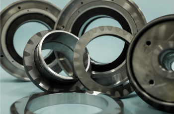
Gear tooth contact pattern
Author(s)TMI Staff & Contributors
Advertisement
A REFINED METHOD BOOSTS THE QUALITY OF TOOTH CONTACT IN GEARBOXES
By Dietmar Sterns
It is important for gears to have the load distributed evenly over the face width during operation at rated conditions. If the load is distributed unevenly, contact pressure and bending stress increases locally, raising the risk of damage. To achieve an even load distribution, precision is needed in designing, manufacturing, assembly and installation of gear units. These elements are checked, tested and inspected at the gear vendor’s shop.
Proper installation in the field is the final step in ensuring acceptability of gear tooth contact. It is vital to ensure that the casing does not get distorted during installation on the baseplate as this leads to bad tooth contact, uneven load distribution, local tooth overload and potential tooth failure.
Figure 1. Schematic of a gear set in a casing lower port
b: gear face width in mm
B: gearing span in mm
CD: center distance in mm
H: Casing height in mm
L: distance between teh reference bars (length of the casing) in mm
W: Casing width in mm[/caption]
Under ideal circumstances, gear shafts are parallel with the load uniformly distributed in the gear mesh when running at rated condition (Figure 1). However, the casing can be distorted when the anchor bolts are tightened. As a consequence, the gear shafts may not be parallel.
Assuming one corner of the casing is lifted upwards due to bad contact between casing and baseplate, the casing would be twisted. Both rotors would be out of level, too. To determine tooth contact deviation, the difference between these angles must be calculated.
With this value known, the gear manufacturer can determine the influence on the load distribution and the allowable load for the gears. The gear manufacturer checks the tooth contact pattern in the factory while the casing was not distorted. Achieving the same alignment on site makes sure the tooth contact pattern is equivalent to manufactured condition.
The lower casing part of the gear unit has two reference bars (Figure 2). These are precision cylinders with a diameter of 25 mm and a length of 160 mm positioned on the two sides of the gear unit parallel to the gear shaft axes. Each bar has a washer mounted on one end. A precision shaft spirit level has to be positioned on the bar, with the flat side pushed to contact with the washer.
Gear case leveling
Steps A to F in Figure 2 show how to proceed for the check of the gear casing leveling.
1. Use a wrench to remove the cover plates that protect the reference bars (2A). Screw the cover plates to the same spot on the casing, but rotated upside down (2B, C). Remove anti-corrosive agent and clean the reference bars.
2. Apply temporary tags on the casing and the cover plates indicating the location of the reference bar and orientation of the gear within the unit.
3. Place the shaft level on one reference bar and check the level (2D, E). Make sure the flat side of the shaft level is pushed to contact with the washer. Take a picture or make a sketch of the level. Make sure the tags are visible or that the sketch indicates the location and the orientation.
4. Place the shaft level on the other reference bar and check the level. Make sure the flat side of the shaft level is pushed to contact with the washer. Take a picture (2F) or make a sketch of the level. Ensure the tags are visible on the picture or the sketch contains information about location and orientation.
5. Compare the two readings. The difference between the two readings indicates the distortion of the gear casing, and a potential misalignment in tooth contact. That difference must be within the tolerance specified by the gear unit vendor.
Several conditions should be fulfilled when performing the check with the precision shaft level. The length of the shaft level must be at least 150 mm. The reference bars and spirit level must be clean. The spirit level must have the same orientation when placed on each of the two reference bars.
The gear unit manufacturer performs the same level check twice during manufacturing: once while casing is open and once when closed. The difference between the readings taken at the reference bars has to be within the specified tolerance. On site, it is enough to perform the check without opening the casing.
This method of casing leveling check can also be applied to other machinery components like motors, generators, pumps, compressors, turbines, extruders and base frames. If the component is large, more reference bars can be used.
Case study
A gear unit rated for 7,500 HP at an input speed of 1,800 rpm and an output speed of 11,808 rpm was delivered for a motor-compressor application with variable speed. Before the start of a string test at the compressor manufacturer, the gear casing was not properly aligned on the test stand. The deviation was 0.12 mm/m, exceeding the design limit of 0.02 mm/m specified in the gear unit manual. Accordingly, tooth contact was compromised.
The ability of the gear unit to handle part load conditions (23%) even with the internal misalignment revealed by the level check was a concern. The angular deviation between the two gear shafts (internal misalignment between the shafts) was calculated.
By taking that value and the reduced load of 23% of nominal torque into account, it was possible to demonstrate that the maximum local contact stress on the gear flanks as well as the maximum local bending stress in the teeth were still below the allowable stress numbers.
It was approved to run the string test at no load and part load with the gear unit as installed. The string test was performed successfully. After the test, the gears were visually inspected through the inspection hatch. It was confirmed that the gear flanks were still in perfect condition.
Deitmar Sterns is the Head of the Engineering Department for High Speed Gears of Renk where he is responsible for mechanical engineering and rotordynamic analysis of high-speed gear units.
Articles in this issue
about 6 years ago
Rotoflow Turboexpandersover 6 years ago
Can natural gas generation survive?over 6 years ago
PowerGen EU shifts emphasis from fossil fuels to renewablesover 6 years ago
Myth: You can always learn something from failureover 6 years ago
R.I.P. POWERGEN EUROPEover 6 years ago
How to mitigate failure mechanisms caused by residual stressesover 6 years ago
PowerGen Internationalover 6 years ago
Protecting new equipment before installing offshoreAdvertisement
Related Content
Advertisement


Advertisement
Advertisement