
|Articles|May 19, 2016
PROTECTIVE COATINGS
Author(s)Drew Robb
Advertisement
EXTENDING THE SERVICE LIFE OF ROTATING EQUIPMENT
By TRAVIS COCKRELL
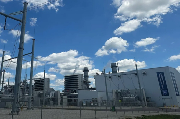
Figure 1: Protective coatings help to increase the efficiency and extend the service life
of the gas turbine[/caption]
Turbines, compressors and pumps are subject to environmental conditions that contribute to corrosion, erosion, fouling and temperature-related issues. It is possible to reduce this degradation by selecting the correct coating system. The first step is to understand the operating environment of the machinery. From there, the sources of degradation can be classified and specific coating systems can be used to increase efficiencies, lengthen the interval between scheduled maintenance and reduce the occurrence of unscheduled maintenance events (Figure 1).
The flow path of air and fuel through a gas turbine (GT), for example, present different conditions that can have an adverse effect on the turbine’s performance. The combination of heat, microscopic abrasives and a gradually increasing concentration of corrosive elements can cause damage to a once-smooth airfoil surface. As the surface finish slowly degrades, the efficiency of both the compressor and turbine are reduced. This process can be arrested in the compressor section and the surface finish restored by the application of suitable metallic coatings. An aluminum base layer is typically used in GT compressors for corrosion of ferritic and martensitic steel components in moist conditions. Small scratches on the surface layer are less likely to cause corrosion.
Galvanic protection is produced by spraying a slurry of aluminum and an inorganic binder, rendered insoluble by a medium-temperature baking process. This layer can then be covered by a harder layer that could include metals, such as chromium. The harder layer is usually applied using spray-coating methods, such as Physical Vapor Deposition (PVD), Chemical Vapor Deposition (CVD), Air Plasma Spraying (APS), Low Pressure Plasma Spraying (LPPS) or High Velocity Oxygen Fuel (HVOF). Selection depends on the coating thickness required and the sensitivity of the part to heat.
Different coatings are needed for hot section components, however, which are made of materials using nickel or cobalt-based superalloys designed to operate in high temperatures. These alloy compositions are less suited to providing corrosion and oxidation protection. They need to be supplemented with custom coatings in higher temperatures when the process of oxidation causes a layer of metal-oxide to form on the surface, which, in general, protects the underlying material. The oxidation process slows down as the thickness of the oxide layer increases. This process can be replicated with the intentional formation of oxides that provide a protective layer preventing further atmospheric attack. Corrosion of a GT component usually occurs in one of two ways.
Hot corrosion may take place between 1,450°F and 1,650°F and it attacks the entire surface. Alternatively, corrosion at cooler temperatures is more localized and tends to create distinct layers of oxide and exposed metal. Further damage can be caused by erosion which involves repetitive mechanical abrasion by particles in the air stream. Standalone HVOF-applied MCrAlY coatings are sufficient to combat corrosion and oxidation at lower firing temperatures. For higher firing temperature GTs, the combination of a MCrAlY bond coat coupled with a ceramic thermal barrier coating (TBC) will reduce the surface temperature of the substrate, and the degenerative effects of oxidation and corrosion.
Compressors
While GTs extract energy from a gas expansion process, turbofans and compressors are used to increase the energy of gases. As such, the main issues with these components are corrosion, erosion and fouling. Many metals form oxide layers that adhere to and passivate the surface to prevent further corrosion, but the change in the physical properties of the surface increases frictional properties and decreases aerodynamic efficiency. Thus there is a balance to be struck between protection and efficiency, which is where coatings can help.
Particulate fouling results from the presence of small particles in the ingested air streams that can cause a distortion to the oncoming laminar flow. Fouling degrades flow capacity and can reduce the efficiency of the equipment in a short period of time. This is a particularly serious in the oil & gas industry where sticky hydrocarbon aerosols are constantly present. In the harshest of operating conditions, solid and liquid particles can pass through the equipment causing erosion. This can lead to material loss, a drop in aerodynamic efficiency, premature blade or vane replacement and failure.
In operating conditions where both erosion and corrosion are present, corrosion can be the primary source of attack by weakening the substrate surface. Once corrosion has initiated, the substrate is more easily eroded, that being the secondary source of degradation. Modern coating technology can now be applied to legacy equipment that was not designed for particulate-laden gas streams. In this way, the original surfaces can be restored and upgraded with improved antifouling and corrosion resistance. Implementing a new coating as part of a refurbishment project can raise performance and reliability (Figure 2).
Figure 2: Modern coating technology can now be applied to legacy equipment that was
not designed for particulate-laden gas streams[/caption]
Coating processes Oxidation and corrosion-resistant coatings are usually aluminides applied by a variety of thermal spray or surface deposition techniques. Corrosion resistant coatings will also use an aluminum base coat that is designed to be conductive, allowing for cathodic protection. The aluminum becomes the sacrificial element and therefore protects the less active base metal component. The electrons flow from the aluminum to the base substrate, which becomes negatively polarized and protected against corrosion.
Basic thermal spraying and PVD or CVD techniques allow for different coating thicknesses, but also have application restrictions. Spray techniques can be used to apply a thicker layer, but need a relatively flat surface and direct line-of-sight in order to accurately apply consistent coating thicknesses. Deposition techniques typically produce a thinner layer but can more easily coat complex shapes. The thermal spraying process involves heating a material in powder or wire form to a molten or semi-molten state.
The material is propelled using a stream of gas or compressed air toward the material to be coated, or substrate, creating a new surface structure as it impacts. The coating materials can be melted using several different processes, including HVOF, plasma spray and electric-arc delivery systems. The process can take place under standard atmospheric conditions or in a highly controlled atmosphere.
Applications include protection from wear, high temperatures or chemical attack, as well as providing a substitute for chromium. Coatings can be metallic, ceramic or any combination required to meet a broad range of physical criteria. For applications that require improved anti-fouling protection, coatings can be applied to stationary and rotating blades, as well as diaphragms, guide vanes, rotors and impellers. Coatings can be tailored to specific applications and include an aluminum base coat for corrosion protection as well as an inorganic sealer and a specialist nonstick final layer (Figure 3).
Figure 3: Turbomachinery coatings can be tailored to specific applications and include an aluminum base coat for corrosion protection and a specialist nonstick final layer[/caption]
These anti-fouling coatings have a thickness between 75 and 125 microns and use polytetrafluoroethylene (PTFE), which gives excellent chemical resistance in low-tomedium temperatures with a maximum operating temperature of 550°F. PTFE offers protection from chemical attack from substances with a pH between 3 and 9, as well as resistance to many solvents and fuels. For specific applications that require protection beyond these characteristics, more specialized coatings can be formulated. It has to be remembered, however that the application of a coating has the potential to upset the balance of a turbine or compressor, even if it is only a few microns in thickness.
The component being coated must be checked for balance both before and after the protective layer is applied. Coatings designed to provide high temperature corrosion resistance are often applied using a HVOF gun, which produces a dense coating with high bond strength. Due to the precision required in manufacturing and maintaining high temperature turbine blades, these coatings should be applied using a robotic manipulator with automated thermal spray equipment. Balancing should then be carried out after rotor assembly.
Clearance between the rotor blades and the stator casing plays a key role in reducing losses in the power train, and in determining the efficiency of the GT. Zirconia-ceramic materials can be used to minimize this clearance in high-temperature applications. Clearance-control coatings or abradable coatings function by allowing a rotating part, such as a blade to cut a path in a sealing abradable layer with minimum clearance. Many of the latest GTs use a thick ceramic coating to impart both thermal-barrier and abradability properties. Protecting hot section components can be challenging when the temperature of the combustion gas is higher than the melting point of the base materials. A combination of internal cooling ducts and TBC can maintain the desired component temperature.
In addition, the latest turbine blades are designed with as many as 500 tiny cooling holes, which must remain unaffected by the coating process. Conventional thermal spraying processes can block off many of the holes, rendering the cooling system almost useless. Newer techniques ensure that none of the cooling ducts are closed off.
Author: Travis Cockrell is Component Superintendent of the Coating Department at Sulzer’s Houston Service Center, which is part of Sulzer Rotating Equipment Services. For more information on Sulzer, visit www.sulzer.com
Advertisement
Related Content
Advertisement


Advertisement
Advertisement
Trending on Turbomachinery Magazine
1
Myth Busters: You Cannot Avoid Compressor Reverse Rotation
2
Baker Hughes Expands NLNG Turbomachinery Support for Train 7
3
Chevron, Microsoft Advance 2.67-GW Gas Power Hub for West Texas Data Center
4
Why Turbomachinery Still Matters in a Renewable Europe
5