Turbo Expo 2019
ADDITIVE AND SUBTRACTIVE MANUFACTURING, CLEAN
POWER, LIQUEFIED NATURAL GAS, WET GAS COMPRESSION
AND SPACE TRAVEL
DREW ROBB
The 2019 American Society of Mechanical Engineers (ASME) Turbo Expo took place in Phoenix, Arizona. As ASME’s premier turbomachinery conference and exposition, it featured over 300 sessions of 1,000+ papers and more than 80 panel, tutorial and lecture sessions.
The best and brightest minds of the industry assembled to share the latest in turbine technology, research & development and application. Speakers from NASA Glenn, EPRI, Integrated Inspection Systems, FLC Flowcastings, Intech DMLS, Doosan ATS America, John Crane, Bechtel, Southwest Research Institute, Baker Hughes GE and others covered a lot of ground. Hot topics included additive and subtractive manufacturing, clean power, LNG, coatings, materials, wet gas compression, waste heat recovery, the future of gas turbines and space travel.
Janet Kavandi, Director NASA Glenn Research Center, briefed the opening keynote crowd on a new lunar program named after Artemis, the twin sister of Apollo and goddess of the moon. NASA Glenn is providing power and propulsion elements for the space ship as well as the Lunar Orbital Platform-Gateway, which will function as a lunar-orbit space station, a solar-powered communications hub, science lab, a short-stay habitation module and holding area for spacecraft.
“We plan to land on the moon by 2024,” said Kavandi. Beyond the space program, NASA Glenn has set its goals on reducing energy use in aircraft by 60%, emissions by 90% and noise by 65%. Innovations in meeting these targets include:
• Embedding engines inside the wings or fuselage to reduce drag and increase efficiency
• Developing an integrated inlet and distortion-tolerant fan for an aircraft engine
• Raising the power density of the engine core using Ceramic Matrix Composites (CMCs) that can withstand and radiate high temperatures.
In addition, an icing project seeks to characterize the icing environment, as well as its impact on aerodynamics and engine performance. Simulations are being done of ice growth on aircraft using wind tunnels and computational models. The findings will improve icing-protection technology.
Subtractive or additive?
Additive manufacturing (AM) has gotten a lot of attention lately. That is understandable, given the greater accessibility and affordability of 3D printing equipment. Yet traditional or subtractive manufacturing remains the dominant approach in turbomachinery. Whether through the use of casts, molds or metal fabrication, subtractive manufacturing accounts for the vast majority of components and equipment.
Metem, a specialized supplier of machining and assembly of turbine super-alloy components, uses a variety of subtractive manufacturing techniques, including Electrical Discharge Machining (EDM). Lucas Guarino, Senior Manufacturing Engineer, explained the process. In EDM, a spark discharges and melts material which then floats away. This works well for slots, holes and cavities in hard-to-reach areas, he said. EDM is also used for fast-hole drilling and milling which is best for complex profiles and drilling holes. Milling and drilling can be done with the same tool.
Electro Chemical Machining (ECM), said Guarino, is good for holes, slots, cavities and contours on metals. Shaped Tube Electrolytic Machining (STEM) is used to produce cooling holes in gas turbine blades and vanes. It is a de-plating process where the electrolyte conducts an electric current from the workpiece to the tool, he said. As the electrolyte streams through a small machining gap, the tool produces precise geometries without contacting the workpiece metal being machined.
Traditional machining provides straight holes. The latest techniques can provide curved holes with a tight radius, such as S-curves and holes that are not round. “STEM drilling can put shapes into the cooling holes, such as little ridges to improve heat transfer by swirling the air in the holes,” said Guarino. “You can improve heat transfer by up to three times by introducing swirling.” Metem also has a drill-through coating process, which can drill through a part with a thermal barrier coating (TBC).
Kenneth Morgan, Casting Engineer, Integrated Inspection Systems, talked about final machining of parts with complex geometries. His company offers MetBase software for coordinate measuring machining, which also includes computer numerical control functionality to deal with the dimensional variability in parts. Traditionally, a six-point nest is the preferred technique to prepare a part for machining. This works well on smaller parts and those with limited variability.
For the complexity of many modern components, Integrated Inspection Systems uses a point cloud (dozens or even hundreds of points surrounding the object) to more precisely measure each part. The company guarantees cutting to 1,000th of an inch. Morgan gave the example of machining a 3rd stage vane. A single gate would take two hours to fit manually. MetBase reduces this to 20 minutes. Parts can be turned around in less than 48 hours.
Steve Rauch, Casting Manager at FLC Flowcastings, covered the process used in investment casting. A ceramic core is made first and then wax is injected into it to produce a pattern for casting. Once the cast is made, post-cast cutting, and finishing is done. His company uses a rapid-machined-pattern process that reduces production time from 370 to 220 days for a gas turbine blade casting core. Traditional manufacturing also continues to play an important role in the production of many components.
Blake Fulton, Prototype Leader at GE Advanced Manufacturing Works, deals with 3D printing, ceramic components and process optimization. Ceramics, he said, are used for thermal coatings, ceramic matrix composites and castings.
Traditional hot gas path manufacturing is still used to create turbine blades, nozzles, vanes and shroud tiles. Additive Manufacturing parts are on the rise. Instead of making hundreds of sets at one time as was the norm in the past, dozens can be made with 3D printing to satisfy the market.
“Materials behave differently when 3D printed as compared to cast,” said Fulton. “Additive manufacturing gives us enhanced cooling, better combustion mixing and reduces post-cast operations.”
It is also making it possible to achieve tighter tolerances, add new features, raise higher firing temperature, and minimize cooling airflow by improving the distribution of cooling channels in blades. 3D printing has many benefits when making hot-gas-path components: larger parts with smaller features, tighter clearances, thicker coatings, less leakage, more cooling holes that are smaller, smaller batch sizes, more exotic materials and concurrent engineering. And more trials can be conducted up to the last minute as opposed to the old pattern of design, then engineering, and then manufacturing.
“The additive age will continue to enable new capabilities and products, and hot gas path manufacturing will continue to be optimized,” said Fulton. “Materials are now moving beyond conventional superalloys. However, the cutting and finishing of 3D printed parts still needs to be improved.”
Coatings
Oxidation coatings extend the life of gas turbine blades, said Dheepa Sriniivasan, CTO at Intech DMLS. Her company developed a process to extend the life of coatings from 3 years to as long as 15 years using a rejuvenation heat treatment process. These coatings interact with the atmosphere and superalloys, she said.
Internal coatings range from 50 to 100 microns. External coatings range from 250 to 300 microns. She offered an alternative to recoating of blades. A cold-spray coating process is used to spray metal powders at supersonic speeds to add material for part repair. As no heat needs to be applied, this coating can be applied as thick as 1 inch.
Digital twins can also extend the life of aeroderivatives, said Ashok Koul, President of Life Prediction Technologies. A digital twin mirrors and simulates the operation of a component, an asset or a system of assets. It can be used to optimize system design, assess life cycle, detect anomalies and optimize performance.
Koul said there are two types of digital twin. A data-driven digital twin targets operational data from the engine, massages the data and recognizes patterns to build a twin. A model-based digital twin is created independently of physical engine data and made to match it.
His company offers the XactLife GT digital twin software to help in trending, pattern recognition and determining component efficiency. It uses microstructure-based damage models that can quantify material changes. It provides 3D thermodynamic semi-empirical analysis and finite element modeling of turbine components, blades discs and vanes.
“A quantitative damage analysis is necessary to make sound maintenance decisions,” said Koul. Manufacturing considerations impact life extension, said David Day, Principal Engineer at Doosan ATS America.
Stainless-steel parts become sensitized when exposed to high temperatures. Sensitization is the precipitation of chromium carbide into the grain boundaries that leads to corrosion and cracking. Solutions include stainless steel made with less carbon, and the addition of titanium or niobium to preserve the chromium.
Day noted that there are always trade-offs with alloys. Alloys that provide longer life for a part may also be very difficult to repair or weld, and the cost may be much higher. There may also be a trade-off between maximum stress and fatigue life, based on the choice of heat treatment.
“A fine grain in blades is better for strength and fatigue, but a coarse grain is better for creep,” said Day. “You have to consider both the chemical composition and the manufacturing process.”
Dry gas seals
In the oil and gas industry, pipeline compressor emissions have been identified as an important source A lively session on materials, manufacturing and coatings was well attended of methane released into the atmosphere. Wet seals (oil seals) are unable to meet new targets being set for methane emissions.
“One strategy to reduce methane emissions is to replace oil seals in existing centrifugal compressors with dry gas seals,” said Christina Twist, Team Leader Gas Seal Development at John Crane.
As wet seals are typically compact in nature, there is flexibility in how they can be installed into a compressor. Dry gas seals, on the other hand, generally occupy a larger cross-sectional footprint. Therefore, said Twist, it was necessary to develop a gas seal that could be retrofitted into the same cavity without the need for machining of the compressor shaft or housing.
The narrower cross section of this John Crane dry gas seal design can replace wet seals within older centrifugal pipeline compressors. Converting to the new seals minimizes wear, lowers operating costs by removing oil-seal supporting systems, reduces energy consumption due to the shear losses associated with oil seals, cuts down on maintenance costs and reduces emissions. This dry gas seal can provide sealing at maximum pipeline compressor duties of up to 120 barg and 100 m/s.
The smaller cross section of the rotating (mating) and stationary (primary) sealing faces required finite element analysis and computational fluid dynamics simulations to optimize the seal design and groove patterns, said Twist. They have undergone testing through the performance envelope for pressure, speed and temperature, as well as testing to replicate seal lifetime.
“Tests of this narrow cross-section seal showed less than 15% of the leakage commonly seen in wet seals,” said Twist.
LNG liquefaction
George Orme, a Consultant for Berkshire Hathaway Specialty Insurance, lectured on how property risk assessments are done for LNG liquefaction plants. Large gas turbines, compressors and heat exchangers operate under extreme conditions and any failure can be catastrophic.
One metric is probable maximum loss (PML), which relates to a single event with adverse conditions. This might be one active protection system impaired while the others are operating. Replacement costs are needed and the business interruption amount (by far the largest value) have to be calculated.
For example, PML would be used for a foreign object entering the compressor, or high cycle fatigue failure. Another metric is Maximum Foreseeable Loss (MFL). This concerns a single event with no protection and no response. As a result, it is costlier. It also requires debris removal, pollution control and other actions.
An example of MFL might be overspeed resulting in mechanical failure with significant damage requiring major repairs or replacement. Orme gave the example of two plants. One consisted of two trains with 14 MTPY capacity. Each train has three refrigeration stages. Each stage has two 50% capacity GT compressors. The PML for this plant turned out to be $3.5 billion to cover replacement and business interruption whereas MFL would be $12.7 billion
The other LNG plant used a spiral wound heat exchanger shared by many systems. This heightened its exposure to risk or its 7 MTPY train with one main refrigeration stage. Two 50% capacity compressors have helper electric motors. Its PML was calculated at $3.5 billion, and its MFL at $8.0 billion.
“Potential loss increases almost linearly with respect to plant net output,” said Orme. “The rate of increase is higher for MFL.”
High-pressure single-shaft boil-off gas (BOG) centrifugal compressors with synchronous motor drives are often used in LNG liquefaction plants. As LNG trade increases, owners look for ways to lower costs through economies of scale, said Matt Taher, Principal Engineer at Bechtel’s LNG Technology Group. “The larger overall output of an LNG liquification plant typically results in higher rates of BOG,” said Taher.
Depending on the LNG process technology and the rate of BOG generated in the LNG storage tanks, BOG can either be recycled to the liquefaction units and re-liquefied or compressed at higher pressures and used as fuel gas for turbines.
BOG compressors are used to maintain and control the vapor pressure in the LNG tanks resulting from flashing of the liquefied natural gas in different operating modes. While the required pressure ratio of BOG compressors varies in a narrow range, BOG flow rate swings significantly as operating modes switch between loading and holding said Taher.
This is a major factor in facility design. Large synchronous motors used as drivers of BOG compressors can be used to generate reactive power to improve the power factor of the plant.
“The use of synchronous motors for power factor correction may also eliminate the need for reactive power compensation by capacitor banks,” said Taher.
The low inlet temperature to the BOG compressor results in high machine reference Mach number, which amplifies the effect of aerodynamic stage mismatching as gas flows thought multiple stages of the compressor.
“The use of adjustable inlet guide vanes (AIGV) is an effective regulation method for high Mach number multistage compressors,” said Taher.
At the Darwin LNG plant in Australia, for example, its 188,000 m3 LNG storage tank has continuously generated BOG. This can cause flashing as the gas approaches the LNG tank pressure. The BOG compression system, therefore, is mainly there to manage the pressure inside the tank. BOG can also be used for GT fuel. Ship loading produces the most BOG, but it is also produced when the tank is in holding mode.
“The flow rate of BOG can swing significantly as operating modes switch between loading and holding,” said Taher. “This is a major factor in facility design.”
At Darwin LNG, the inlet temperature of BOG is 160°C at a pressure of 1 bar and an inlet fl ow of 300 m3/min. The compressor had to be designed with a rotational speed of 8,000 to 10,000 rpm with both the high-pressure and low-pressure compressors running at the same speed.
Waste Heat Recovery
Thermodynamic cycle analysis improves the efficiency of production cycles by selecting the right design, said Clement Joly, Lead Engineer at Softinway, speaking about design considerations for waste heat recovery systems. It is vital to understand the thermo-physical properties of potential fluids before approaching the entire waste heat recovery cycle.
Non-traditional fluids, such as supercritical CO2, R245fa and ethanol each come with their own specific design needs and fluid requirements, he said. Joly compared the net power production in Organic Rankine Cycle (ORC) systems when fueled by ethanol, steam, R134a and R245fa, as well as other factors that must be considered in design.
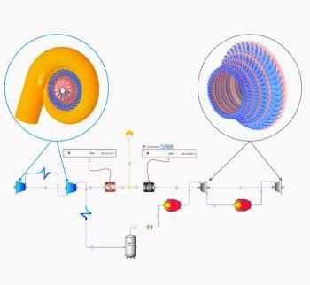
He also delved into ORC costs. SoftInWay’s AxStream was used to analyze eight different configurations to determine the best option for each type of fuel. It offers the ability to design a machine ranging from a turbocharger in a small car engine, to a 125 MW gas turbine or even a turbopump for a liquid rocket engine based on factors, such as size, cost and complexity.
Wet gas compression
Wet gas compression is of growing importance in oil & gas applications. Gas gathering, processing and pipeline operations always produce liquid. The traditional approach has been separation equipment. But a desire to decrease the equipment footprint for environments, such as subsea, has led to designs that eliminate the separator. In these cases, the compressor must be able to cope with wet gas.
Southwest Research Institute (SwRI) has been researching wet gas compression. “Compressor performance in wet gas can vary significantly,” said Griffin Beck, Senior Research Engineer at SwRI.
For example, wet gas performance tests at SwRI demonstrated that, at a low flow rate, there is a slightly higher-pressure ratio than with dry gas, but as the fl ow increases, the pressure ratio is lower than dry gas. He added that extra power is needed to deal with loss of pressure ratio and lower compressor efficiency.
To cope with sub-synchronous vibration issues in wet gas compressors, a labyrinth seal was replaced with a pocket damper seal. Erosion and corrosion also have to be factored in due to the presence of liquid, said Griffin.
“Scrubbers are often used to eliminate or minimize liquid in the compressor,” said Giuseppe Sassanelli, Senior Engineering Manager, Baker Hughes GE. “But it is better to have a compressor that can handle a larger amount of liquid.”
Baker Hughes GE has developed a wet gas compressor. The WBCL302/A prototype has been running in a test rig in Norway for more than 1,000 hours of harsh qualification. Its Liquid Mass Faction (LMF) ranges from 0–30% and its Liquid Volume Fraction (LVF) from 0–3%. The suction pressure is from 20–110 bar “There is lots of complexity in measuring performance when there is so much change in LMF and LVF,” said Sassanelli.
Some of the features of the compressor include two stages, an impeller made of IN625m with an IGV multilayer coating of TiN, seal teeth on the rotor, internal extraction for DGS and shunt holes, as well as swirl brakes at the impeller eye.
BHGE compared the performance of dry gas and wet gas. The dry gas maintained a vibration level below 20 microns with no sub-synchronous vibration. The wet gas compressor showed the presence of some sub-synchronous vibration and a small increase in overall vibration. But this was not enough to cause any rotor instability issues. BHGE also wanted to eliminate the possibility of the thrust load variation when LMF increased.
Testing showed that despite big changes in LMF, the amount of thrust stayed the same. However, pressure ratio (PR), power consumption as well as head rise to surge increased along with LMF. “Water washing recovers performance lost due to fouling,” said Sassanelli. “For a fixed compressor operation point, operating at 30%, LMF results in a lower operating speed, a small increase of power and a rise in pressure ratio,” he said.
From wet gas compression, attention shifted to wet compression, i.e., intentionally sending fog-saturated air into the compressor to lower inlet air temperature, increase mass flow and boost power output. Wet compression is used on 30% of our 1,000 fogging systems, said Tae Lee, Regional Sales Director at Mee Industries. The system can be deployed within four months during an outage of one-to-three days. Installed and operating costs are low for an average power boost of 8 to 10%.
He offered safety tips for wet compression and fogging:
• Fogging nozzles should be wired to prevent foreign object damage
• Droplets should be maintained at a size of 20 microns or smaller to avoid blade erosion
• Nozzles should evenly distribute fog and avoid air-flow-induced vibration
• Drainage systems should be installed to eliminate standing water
• Drainage should be monitored through a viewing window.
He gave the example of the Watson Cogen plant in Southern California, using wet compression on its GE 7EA turbines. “After more than two decades, fogging has caused no blade erosion at the plant,” said Lee.
Next year’s Turbo Expo will be in London, England.
Newsletter
Power your knowledge with the latest in turbine technology, engineering advances, and energy solutions—subscribe to Turbomachinery International today.

