
|Articles|November 16, 2021
- September/October 2021
Compressor choke
Author(s)TMI Staff & Contributors
Choke prevention in axial compressors.
Advertisement
BY ROMAN BERSHADER
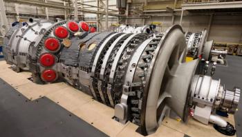
Axial compressors are used in processes where a large amount of gas is required, providing high efficiency relative to their size. Industrial applications include first-stage mixed refrigerant compressors in LNG plants, main blowers in refineries using the catalytic cracking process, and blowers for blast furnaces in steel mills.
There are two restrictions on the operation of dynamic compressors caused by different phenomena: at relatively low flow rates - surge; and at relatively high flow rates, a choke or a stone wall. These conditions must be taken into account in design so they can be prevented.
Due to the severity of surge and the much higher likelihood that compressors will operate at relatively low flow rates, this issue has received more attention. The surge phenomenon can be described as erratic operation accompanied by strong mechanical vibration, rotational speed fluctuations, pressure fluctuations, gas velocity fluctuations, and rapid temperature rise with possible overheating and abnormal sound generation. The choke phenomenon can be defined as increased vibration, temperature rise, and a rapid drop in efficiency. If the choke is not as strong as the surge, prolonged operation in the choke zone may damage the compressor.
Both surge and choke are fluid mechanics phenomena that occur in compressors under certain circumstances. Dynamically unstable compressor operation due to surge or rapid efficiency drops due to choke can occur at different speeds, inlet pressure, inlet temperature, and different molecular weight of gases (in LNG applications). Therefore, the theory of experimental fluid mechanics must be applied.
The principles of similarity and dimensional analysis are used to generate modified dimensionless compressor maps with fixed surge and choke limiting lines for all inlet conditions, gas compositions, and rotational speeds, which can then be used in various surge and choke protecting algorithms. The most commonly used dimensionless coordinates of such maps are compression ratio and corrected mass flow rate.
Close-loop PID controllers are typically used to regulate anti-surge valves to protect compressors from surge, and to regulate inlet guide vanes (IGV) or outlet valves to prevent compressor choking by comparing the controlled variable (CV) to the desired SP setpoint. There are various compressor protection algorithms that calculate the CV that characterizes the position of the operating point relative to the choke line, represented in dimension-less rectangular coordinates.
The most commonly used choke protection algorithm in industrial control systems, or its derivative, defines the CV (%) as the distance from the operating point to a point on the choke line at the same compression ratio. Other algorithms define the CV (%) as the distance from the operating point to the point on the choke line at the same mass flow. In rectangular coordinate systems, the distance between points on a curve and the curve itself are projections onto a horizontal or vertical axis.
The first algorithm requires extrapolating the choke line so that the vertical coordinate passes through it. Compressors are selected to operate at points with maximum efficiency, somewhere between the surge point and the operating point OP (Figure 1) in a curve where the accuracy of calculating the controlled variable to protect compressor from choke is minimal, since the position of the point (B)Rc is an assumption. The accuracy of the operating point calculation increases as the choke point is approached, but may still be inaccurate within the safety threshold.
Algorithms of the second type seem preferable, since the projection of the operating point on the horizontal axis always intersects the choke line. In such algorithms, the displacement of the operating point is determined by the vertical coordinate of the compression ratio as a function of the horizontal coordinate of the corrected mass flow rate, then a small change in distance between the intersection point (B) on the choke line and the choke point can significantly change the distance, which makes it difficult to tune the PID controller for its fast response.
Setting the safety threshold in rectangular coordinate systems can only be made relative to the choke line, since the entire operating range is not available. The compressor performance curves on the plane are geometrically limited to perpendicularly oriented lines to reproduce the entire operating range from the surge point to the choke point, which is achievable in a polar coordinate system defining this range as a rotation from the polar angle to the polar angle. Therefore, the controlled variable CV (%) for the choke protection controller can be calculated as the choke point polar angle minus the operating point polar angle divided by the entire range, which is equal to the choke point polar angle minus the surge point polar angle.
Polar coordinates provide the most accurate representation of the operating point in relation to surge and choke limits, reproducing the full range of operating points at which the safety threshold control setpoint can be set exactly as required. And the controlled variable calculated in the polar coordinate, is an almost linear variable, which makes it easier to tune the PID controllers.
Articles in this issue
over 4 years ago
Resolving varnish challengesover 4 years ago
Methane emissionsover 4 years ago
Q&A: The need for oil-free compressionover 4 years ago
Vendor spotlight: FS Elliottover 4 years ago
The economics of hydrogenover 4 years ago
Carbon capturealmost 5 years ago
Turbine fuel controlalmost 5 years ago
Myth: New turbomachinery is always better than older machinesalmost 5 years ago
Turbo tips: High-pressure turbocompressorsalmost 5 years ago
Western Turbine Users part IIAdvertisement
Related Content
Advertisement


Advertisement
Advertisement
Trending on Turbomachinery Magazine
1
DOJ Intervenes in xAI Gas Turbine Lawsuit, Citing National Security
2
EnergyLink International Expands AQCS Capabilities to Large-Frame Gas Turbines and Coal-Fired Power Plants
3
EU Methane Rules Raise 2027 Supply Risk for Gas Exporters
4
Reliable Engineered Materials for Turbomachinery Equipment
5