Condition monitoring of steam turbine generator governing systems
The governing and control system of a steam turbine generator controls the entry of steam during starting up to service speed and provides close speed control for synchronization to the electric power system. Once synchronized, the governing system controls the output of the machine. It also provides machine protection, typically using various devices to initiate a trip in emergency conditions. Here, we focus on a system with the turbine generator in normal loaded service.
Wear leads
These systems can include several mechanical linkages and wear can lead to erratic load performance in service. An example was a 200 MW machine that showed unacceptable load variations of ±25 MW. On this machine, the speed governor sleeve movement from zero to full load is 3.6mm. Off-load, 750µm of slack was measured. This explained on-load variations.
Experience has demonstrated the importance of sharp edges on the piston-type spool valves used in these systems. A turbine with erratic governor performance was found to have its governor output spool valve piston edges slightly rounded, as well as having a small nick, presumably from overhaul work. Replacement with the spare resulted in satisfactory performance.
These variations in performance can usually be smoothed out by using an over-riding control (typically called a load limiter). However, this negates the machine’s response to frequency variations. All other machines on the system would take more than their share of the increased load.
The overall speed regulation of the governing system can be found with a load rejection (or load throw-off) test. The machine should settle at a speed corresponding to its regulation. However, this test does not reveal how well the machine responds to frequency variations during normal loaded service. On-load tests should be done to show how incremental regulation is obtained.
In normal loaded operation, the machine’s governing system responds to variations in system frequency, caused by such incidents as another large set tripping off-line. It is important for electric power system stability that each machine responds in the expected manner according to the intended incremental regulation of the machine. Somewhat similar behavior occurs with a domestic motor lawn mower. When more heavily loaded, operating speed drops. The governor responds and opens the throttle so that speed is recovered.
Off-load hysteresis test
Hysteresis is the phenomenon in which the value of a physical property lags behind changes in the effect causing it; for instance, when magnetic induction lags behind the magnetizing force. A hysteresis test is applicable to any control system with mechanical parts. Starting from a convenient setting, the input control signal is increased in steps in the upwards direction, without reversing the direction of the input. When full range is reached, the input signal is reduced in steps until the minimum setting is reached. The signal is then increased until the original setting is obtained. At each step, the matching output is measured.
A plot of input versus output reveals the presence of hysteresis and allows its extent to be measured, usually as a percentage range. In governing systems, the input signal is usually a control oil pressure which is given from the speed governor.
The steam control valve position is the output and can be obtained with suitably mounted mechanical dial gauges. The valve stem itself may not be accessible and movement of an operating servo may have to be measured instead. Displacement transducers and electronic pressure transducers of suitable ranges can also be used. These enable data to be collected using a datalogger and computer. Another way using an XY plotter is shown in Figure 1. Valve movement is shown on the vertical scale. The horizontal scale is the control oil pressure. Hysteresis here was negligible.


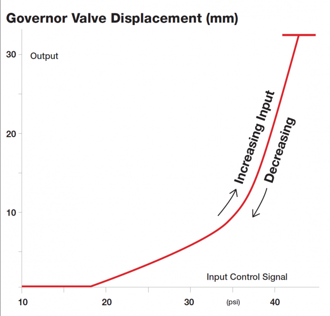
Figure 1: Hysteresis test on a governor valve[/caption]
This test was performed after maintenance. The up- and down-range plots coincide, as would be expected. Test measurements can be made manually. But on large machines, it requires careful coordination of readings if those taking them are not in sight of each other.
On-load testing
Once synchronised, the speed of a turbine generator varies by very small amounts, according to the system frequency. Most sets have 2-pole generators, and in countries with 50Hz systems, operate at 3000 r/min. System frequency is kept within close bounds such that a mean value of 50Hz results. Variations normally do not exceed ±0.2Hz due to sudden load changes (e.g. because of a generator tripping offline) and the mean frequency is normally recovered within no longer than a second or two.
Also known as droop, steady state speed regulation is the permanent change in speed as a percentage of rated speed, when the loading is reduced to zero without changing the speed/load changer setting. Base-loaded, fossil-fired sets will typically have 4% regulation, while peaking hydro sets can be set at 2% for greater relative response. In today’s market environment, a machine could be set at a higher regulation, say 7%, to reduce its response and minimize output variation. Electronic governing systems can have the setting changed easily online, but mechanical governing systems need linkages to be adjusted.
Incremental regulation (also called incremental droop) is the rate of change of steady state speed with load, at any given speed and load. As this can be hard to visualize as applying over the very small system frequency variations of typically only 0.1Hz in either direction from rated frequency, another way is to express it as the amount of load change per 0.1Hz of speed variation.
Case studies
All machines showed extremely high values of incremental regulation. An unexpected outcome was that one machine did not respond at all at one load setting. Incorrect original wiring of the control systems was found and rectified.
Another example concerns the testing conducted on a 350 MW machine with mechanical governor and hydraulic servos. With the load limiter control wound out of effect, load was reduced gradually then returned to maximum. Controls were adjusted in the downwards direction until minimum output was reached, then load was raised upwards. Note that hysteresis cannot be identified and isolated unless this procedure is followed. At each step, the load is stabilized while readings are taken.
On this turbine, movement of the speed governor results in movement of a piston-type valve inside a sleeve. The sleeve has drain ports connected to the control oil system, such that changes in relative displacement between the piston and sleeve directly change oil pressure. This pressure, in turn, positions the steam control valves. This relative port displacement can be obtained by speed governor operation, or once machine speed has reached the speed control range when starting up, by the operator moving the speed/load changer (speeder). Once the turbine generator is synchronised, speed is held at system frequency, and speeder movement changes the output of the machine.
During manufacture, the characteristics of the speed governor are tested and the fly-weight springs adjusted to give the design output of axial movement with speed change. This machine should have had a speed regulation of 4%, which corresponds to 5% load per 0.1Hz of speed variation. Speed change of 4% for a 3000r/min machine is 120 r/min, which corresponds to a load from zero to full output. Over this relatively small speed range, the output of the governor is closely proportional to speed.
For this design, a 4% speed change corresponds to a governor sleeve travel of 7.4mm. Using this approach for other selected values of speed regulation, lines of constant speed regulation can be constructed and drawn on axes of speeder travel versus output, as shown on Figure 2.
On test from 250 MW to 360 MW, the speeder travel was measured using a Linear Variable Displacement Transformer (LVDT). Other transducers were connected to measure displacements of other linkages and servo relays in the system, control oil pressures, inlet steam pressure and other variables. A connection was also made to the main output metering. A data logger was used to record the data at ten-second intervals. Earlier in the life of the machine, these tests were done initially and satisfactorily using manual measurements, but errors can be made when reading small distances with a micrometer under the stress of test conditions (hot and noisy).
The measured load values were corrected to the load expected at standard terminal conditions of steam pressure and temperature. With a printout of data at each 10 seconds, sets of readings can be selected at rated values of temperature and pressure, thus avoiding the need for any corrections.


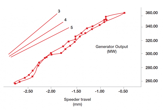
Figure 2: Load vs Speeder /Load Changer travel on test of a large steam turbine generator. Results are shown with gradients of regulation for 3%, 4% and 5%.[/caption]
The variation in incremental regulation with load can be seen by comparing gradient sections of the test curve with the calculated lines of constant regulation (3, 4 and 5 in Figure 2). Incremental regulation can be seen to be close to the design value of 4%, with departure at higher loads. If desired, it can also be read off at uniform intervals of load and drawn versus load. Hysteresis can be observed, measured and expressed as a percentage range: 0.06Hz maximum is desirable.
Summary
Incremental regulation is an important parameter in the performance of the governing system of a steam turbine generator. Simple tests can derive this value on load and reveal any hysteresis in the governing system. Off-load hysteresis tests can be used to examine the relationship between individual components in the system to localize areas requiring maintenance attention. ■
Ray Beebe, OAM MEngSc FIEAust CPEng (ret) worked in fossil-fueled power stations for 28 years in Australia and UK prior to joining academia. He is the author of Steam Turbine Performance and Condition Monitoring. For more information, contact r.beebe@federation.edu.au