
|Articles|June 7, 2021
- May/June 2021
Turboexpander reliability has increased steadily over time
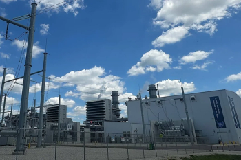
Expander-compressor units provide refrigeration for extracting heavier hydrocarbon components while having low energy costs.
Advertisement
The use of cryogenic turboexpander technology in hydrocarbon processing started in the early 1960s with the utilization of efficient near isentropic expansion (the method at the time was free expansion from a Joule-Thompson valve). For many decades now, radial inflow turboexpanders with booster compressor loads have been a favored equipment choice in natural gas processing. Expander-compressor (EC) units provide refrigeration for extracting heavier hydrocarbon components at the same time as having low energy costs. The main applications are natural gas liquid (NGL) recovery, dewpoint control, liquified natural gas (LNG) pretreatments, and ethylene and petrochemical processes. Refrigeration is provided by expansion through a turboexpander, and the free shaft power is utilized to drive a booster compressor.
As is the case with other turbomachines, turboexpander reliability is a product of component design, manufacturing, design features, control systems, and process environments. The guiding requirements for turboexpanders and centrifugal compressors in the petroleum, chemical, and hydrocarbon gas processing industries are set out in American Petroleum Industry (API) Standard 617. API 617 specifies that expanders should have a service life of 20 years, which includes at least five years of uninterrupted service. In addition, hazard and operability studies (HAZOP) and safety integrity level (SIL) reviews specify required instrumentation to minimize loss of production.
As a component reliability example, magnetic rotor/bearing system reliability is now in the range of 99.5-100% over 100,000 hours of operation with approximately 10 hours preventive maintenance every year. The majority of larger turboexpanders in gas processing, petrochemical, and energy recovery units are built to order, including auxiliary and control systems. The components that are normally custom designed for specific applications are: wheels, inlet guide vanes (IGV), rotor-bearing systems, and seals.
The mechanical development and the performance of turboexpanders have been improved over decades in a number of ways, such as with design tools, analytical methods, and lessons learned from implementations. Robust rotor-bearing systems, both oil-lubricated and magnetic bearings, can handle a wide range of radial and axial thrust loads during normal and off-design operation, as well as unavoidable process upsets. A process of continual impeller and inlet guide vane flow channel optimization ensures a wide operating range with minimal performance penalties. Additionally, recent improvements in IGV actuation systems have allowed smoother process control and better stability.
Turboexpanders in industrial operation
The cryogenic process is the preferred method of separating a heavier hydrocarbon from natural gas. The treated gas is isentropically expanded to lower the pressure, which results in maximum cooling and condensate. The typical single-stage turboexpander pressure ratio is 4:1, but depending on the applied process it could be as high as 14:1. The static temperature is reduced to a cryogenic range as energy is removed. This released energy is then used to recompress the gas feeding the downstream process. In most processes, the turboexpander outlet is in two phases, with liquid mass fraction ranging from 5-20%, and up to 40% in dense phase cases. In this system, the expander wheel flow passage geometry is designed to handle any amount of discharge liquid fraction with no significant performance penalty.
The turboexpander feed is from the top of a separator, which normally contains a small amount of mist carryover. Mist particles are typically carried out with high gas stream velocities, although a high concentration of carryover (>1%) and a formation of large radius droplets at the turboexpander inlet may result in a high impact on the blade tips, which causes erosion in the flow path. Erosion will be more severe if there is a combination of fine dust in the nucleus of droplets. In order to minimize this risk, process industries have established guidelines for turboexpander inlet separator designs and avoiding liquid slug.
A turboexpander bypass or Joule-Thomson (J-T) valve is used for plant operation during the start-up, shutdown, and service period. On the one hand, as a free expansion (isenthalpic) J-T valve, the outlet stream is not sufficiently cooled for liquefaction at reduced pressures. On the other, because the turboexpander process is isentropic, it provides maximum cooling.
Design developments
Manufacturers have encountered various issues that necessitated design and operational guideline improvements. Examples: Inlet guide vane mechanism and control; resonance-free impellers avoiding critical excitations; axial load increased capacity and control; and rotor-bearing system stability.
A turboexpander variable IGV works by converting a portion of process fluid head (i.e. 50%) to kinetic energy (gas velocity). Similar to an efficient control valve, the IGV maintains a desired process setpoint by regulating the volume flow through the expander. In general, IGVs allow efficient operation across wide operating ranges, while they must also be capable of high reliability in harsh process environments.
Basic aerodynamic design guidelines for IGV segments are uniform flow and pressure profile, balanced forces, no flow separation downstream of the throat, and minimizing the passing frequency wake region. Mechanical-related problems were formerly related to excessive force or contact stress applied to pins and linkage, and a clamping of the plates. These are nowadays evaluated during the design process phase, which takes into consideration the range of process pressures and the selection of the actuator size.
Most IGV problems are either: mechanical, such as galling; process-related, such as dust particles and process pulsation; or operation issues, such as actuator position hunting due to a fine control band. Galling wear results in damage to the sliding surface, which in turn causes adhesion and high friction. Nevertheless, IGV galling resistance has been improved by using materials with dissimilar properties, material treatments, minimizing contact stress between moving parts, avoiding deflection of the plates, and by applying suitable coatings compatible with the process media. Some of the process-related issues include stress corrosion cracking in case of sour gas, a high concentration of particulates, and hydrate formation when the hydrocarbon mixture contains water vapor. Operation-wise, IGVs are designed for continuous process control with desired control band bias.
However, in some instances an unnecessary very fine process control band setting results in a hunting of the actuator position. This shortens the life of some IGV components, particularly if some process contaminants are present. Currently, in addition to IGV assembly optimum linkage design, computational fluid dynamics (CFD), finite element analysis (FEA) and metallurgical analyses are carried out during the design phase. In addition, design and component integrity are validated using a stroke test apparatus developed for simulating the galling resistance under applied process pressure forces.
Wheel optimization
The converted static pressure to high velocity in the IGV assembly is further expanded into the wheel, which extracts energy and results in high-volume refrigeration with additional velocity head recovery in the discharge diffuser. Radial inflow turboexpanders are 50% reaction, which means impeller enthalpy drop is about half of the stage enthalpy drop. This provides optimized velocity in the stator and rotor, and it also minimizes the incidence into the radial blades. For a radial stage design with an optimum velocity ratio of 0.7, total efficiency is up to, 90%.
In some applications with high enthalpy drop (above 180 KJ/Kg), design velocity ratio is a lower value due to the mechanical limitation on the turboexpander wheel peripheral speed. For a given throughput, operating the turboexpander at a lower speed or much higher head than design will result in lower production rates. This could be due to off-design process conditions or rotor/bearing mechanical issues, and high vibration. Therefore, rotor/bearing design stability is the key to high reliability.
In addition to stress analysis, the mechanical integrity of the expander depends on the prevention of high-cycle fatigue and avoiding resonance frequencies in its operating range. The basic guidelines for wheel performance design is to ensure a uniform flow and pressure distribution, a good leading-edge flow pattern, acceptable blade loading, and no flow separation.
Hydrocarbon turboexpanders require a wide operating range. Both the mechanical integrity of the turboexpander wheel and the stress loading must avoid creating destructive resonance frequencies. For example, when the IGV discharge excitation matches a wheel natural frequency mode, it will resonate and potentially initiate a crack. Excitation force will increase with a higher fluid density, power and Mach number, and flow instabilities, so higher harmonic interferences need to be considered during the design and final tuning stages.
Rotor-bearing system
The selection of oil or magnetic bearings often comes down to the preference of the end-user. The decision is based on footprint, oil-free operation requirements, oil dilution in case of heavy components in the seal gas, and plant location.
The required load capacity for the shaft support, peripheral speed, process-induced cross-coupling effects, and stability is determined and set by analytical methods. The magnetic-bearing stiffness is about seven times lower than the equal-sized oil bearing, and for this reason larger relative magnetic-bearing sizes are used to compensate for the rotodynamic need. Turboexpanders with magnetic bearings have proven their rotodynamic robustness over several million hours of operation.
There have been several lessons learned from decades of design and operation of magnetic bearings. Two particularly worth highlighting are the importance of protecting the rotor-bearing system from external factors, such as corrosive components in the process gas; and choosing the right bearing size while taking into consideration the process parameter influence on the load capacity.
On oil-bearings machines, lubricant type, cleanness, and diluted oil viscosity after dissolve gas equilibrium are the important factors for reliability. Journal oil bearings could be either fixed geometry or tilted pad, depending on the peripheral speed. Turboexpander oil bearings are a combination of journal and thrust bearings with a positive automatic axial load control.
Turboexpander compressor shaft seals are a labyrinth type. The purpose of the shaft seal is to prevent process gas ingress to the bearing housing and to act as a shield against the cold process side. Warm and dry seal gas with positive differential pressure to the process side is injected into the seal and vented through the bearing housing to the lowest process gas pressure, which is normally the booster compressor suction. The bearing housing and the oil reservoir are pressurized, and the system is enclosed with no hazardous gas leaking to the atmosphere. For magnetic-bearing turboexpanders, shaft-seal clearances are two-to-three times larger than equivalent oil-lubricated machines due to higher bearing clearances. Therefore, in some applications, floating ring seals are used to minimize the seal gas flow rate.
In addition to standard machinery protection, additional features are built into the system that helps categorize this piece of equipment as smart and relatively self-controlled (if desired). These features include automatic thrust load equalizer (ATE) for both oil-lubricated and magnetic-bearing set-ups, automatic IGV control based on process signals, automatic seal gas differential pressure control, and automatic booster compressor anti-surge control. For magnetic bearings, more advanced control cabinet features are available, including remote tuning, a toolbox for bearing health check, hot swap back-up battery change during operation, and two-out-of-three voting on speed.
External process factors
The integration of turboexpander systems into the process environment is as important as using a perfectly designed machine. High reliability is only achieved by careful consideration of all external factors, including the gas conditioning, seal gas selection and the required protective materials. For turboexpanders, ignoring such factors can result in inlet liquid carryover, corrosive components, process pressure fluctuations, incorrect depressurizations, and incorrect start-ups and shutdowns.
As far as the inlet liquid is concerned, and depending on the fluid density and drag forces, it is normal for 1-2% liquid by weight of mist form when entering the casing inlet. It is carried by the expanding gas without erosion impact on the blades. Fluid velocity in the IGV throat is near or over sonic velocity, so large dust-particles impact will erode the IGV flow channel and affect the wheel blade pressure surface.
Some of the external factors affecting IGV operation are particulates, hydrate formation, and a corrosive environment. Additionally, hydrates could form in a turboexpander when there is free water in the process gas. Such hydrates can freeze the IGV mechanism and result in a loss of control, or they could block or collapse the inlet screen mesh, subsequently damaging the components.
In summary, cryogenic turboexpander design and operation has significantly evolved since the first applications of turboexpanders in hydrocarbon processing plants in the early 1960s. Yet there remain opportunities for improvement in performance, operability, and reliability. ■
Behrooz Ershaghi is Marketing and Technology Manager at Atlas Copco Gas and Process. He received his MS degree in petroleum engineering and PhD in chemical engineering from the university of Southern California.
Louis Mann is a Research and Development Manager for Atlas Copco Gas and Process, and he is responsible for new turboexpander product and feature development. Mr. Mann received a BS in mechanical engineering from California Polytechnic State University, San Luis Obispo and is a registered Professional Engineer in the State of California.
Gabe Glynn is the Applications Engineering Manager at Atlas Copco Gas and Process and is located in Santa Maria, California, USA. He holds a BS in mechanical engineering from California Polytechnic State University, San Luis Obispo.
Articles in this issue
about 5 years ago
Piping and Nozzle Loadsabout 5 years ago
Bearings and stabilityabout 5 years ago
Options for Modernizing Steam Turbinesabout 5 years ago
Myth: Additive Manufacturing is the Answer for Everythingabout 5 years ago
Vendor spotlight: Elliott Groupabout 5 years ago
The effect of eddy grooves on tilting pad journal bearingsabout 5 years ago
Fog system upgradesabout 5 years ago
Turboexpander reliability has increased steadily over the yearsabout 5 years ago
Sundyne aligns with net zero goalsAdvertisement
Related Content
Advertisement


Advertisement
Advertisement