What we learned at the virtual Turbomachinery Symposium


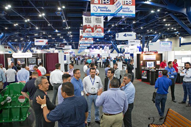
The good old days at the 2019 Turbomachinery & Pump Symposium.[/caption]
The Annual Turbomachinery & Pump Symposium is regarded by many as the premier turbomachinery event. Traditionally set in Houston, TX, the live event was cancelled due to Covid-19. Organizers at Texas A&M’s Turbomachinery Laboratory valiantly battled to provide a virtual version in December of 2020. However, there is nothing like the real thing.
A wealth of sessions made up for the lack of a buzzing exhibition floor. Topics covered included hydrogen compression, seals, gas turbine (GT) performance, combustion, additive manufacturing, turbomachinery in refineries, and operations & maintenance.
Hydrogen compression
Rainer Kurz, Manager of Systems Analysis at Solar Turbines, walked attendees through the performance of the compressor, the combustor and the turbine section during a tutorial session. Also discussed were control concepts for single-shaft and two-shaft machines driving generators, compressors, and pumps.
GT performance characteristics depend on ambient and operating conditions. Consideration must be given to site elevation, ambient temperature, relative humidity, speed of driven equipment, fuel, and load conditions.
Kurz introduced data analysis methods and detailed the impact of degradation on component performance, engine performance, and approaches to mitigation.
His takeaways: Applications for industrial gas turbines will change but will be with us for a very long time. “With or without hydrogen, natural gas will play a key role in the transition towards a more sustainable energy future,” said Kurz.
As engineers seek to adjust turbomachinery to hydrogen service, challenges will inevitably materialize. One such challenge, hydrogen induced cracking (HIC), was the topic of another session.
Centrifugal compression is dependent on gas molecular weight. Aerodynamic head is developed by increasing the gas velocity to raise kinetic energy levels, then by converting the kinetic energy to potential energy through diffusion. The resulting impact is an increase in static gas pressure. The amount of kinetic energy imparted into the gas is a function of gas velocity and molar mass. To achieve high gas velocities, an increase in impeller rotational speed is required. This imparts higher stress on centrifugal impellers, which can exceed guidelines provided by American Petroleum Institute (API) Standard 617, eighth edition (2014).
To utilize the benefits of higher rotational speed, therefore, new strength limits for the application of materials in hydrogen gas compression are required. Svenja Haarmann, Head of Chemistry at Siemens Energy delivered a talk on the HIC resistance of common impeller alloys. She compared them, utilizing National Association of Corrosion Engineers (NACE) standard test method TM0177. The goal was to determine a test procedure and validate higher-strength materials suitable for hydrogen compression environments. Chemistry, microstructure, mechanical properties, and heat treatments were examined to explain the results observed and seek predictors for high-strength materials in hydrogen service.
“HIC can occur in highly stressed materials,” said Haarmann. “High rotational speed is required in hydrogen centrifugal compression to achieve a reasonable head rise per stage, leading to high impeller stresses.”
She noted that, per industry standards, the maximum yield strength for all materials used in hydrogen service is limited to 120 ksi. Test results indicate that this number is overly conservative. Testing reveled that some alloys could perform well at 145 ksi and another as high as 160 ksi. Such alloys, therefore, have high potential for hydrogen environments. Updating industry standards to allow higher impeller stress will allow smaller, faster running compressors in hydrogen service.
Seals
Many sessions at the conference were devoted to seals and especially dry gas seals (DGS). Pipeline sealing, for example, is challenging as you often don’t know what is coming down the pipeline. Therefore, operators are looking for increased reliability and better control of leakage or lost product, during normal opeation and catastrophic seal failures.
Jim Wasser, Global Director of Design Engineering and John Morton, Product Line Director, Advanced Wet Sealing Solutions, John Crane, said most operators use single seals of various kinds on crude duties. When they have to deal with NGLs, seal technology can vary greatly. In North America, for example, conditions can vary between -25°C to +30°C and viscosities from around 2 to in excess of 3,000 centistokes (cSt). Seal chamber pressures can be up to 1,200 psi.
Two years ago, John Crane introduced non-pusher secondary sealing technology to improve seal performance on crude services. That same technology has now been developed into a family of seals capable of handling non-crude liquid hydrocarbon applications.
“Non-pusher secondary sealing technology brings about no change in seal balance in high or low pressure applications, unlike seals utilizing a full convolution elastomer bellows,” said Wasser. “It can flex along the balance diameter and is capable of 0.8 mm shaft axial movement.”
He added that it is robust enough to handle high startup torque and shaft misalignment. No hard coating is required on the sleeve as there is no movement of the secondary sealing element.
Several discussion groups at the show took up seals. Stefan Cich, a Group Leader in the Machinery Section at Southwest Research Institute, led a discussion group on DGS systems. He took attendees through their history, starting in 1970 as a response to the need for a less complex and hazardous system than floating ring oil seals.
“Non-pusher secondary sealing technology brings about no change in seal balance in high or low pressure applications, unlike seals utilizing a full convolution elastomer bellows,” said Jim Wesser, Global Director of Design Engineering.
DGS are used as low-leakage shaft end seals for many centrifugal compressors and other turbomachines. Such sealing technologies help limit leakage. As governments and companies continue to limit carbon emissions, leakage
mitigation grows in importance.
DGS configurations include single seals, tandem seals (sometimes with an intermediate labyrinth seal), said Cich. He also covered fundamentals, turbomachinery applications, and design considerations for reliability.
Seal testing can ensure design conditions are met. Test rigs can study off-design conditions such as transients or contaminant injection. In addition, he offered insight into failure modes specific to heat generation from
liquid contamination.
Combustion Components and Additive Manufacturing
Additive manufacturing (AM or 3D printing) is particularly suitable for making small, complex parts and components, especially within the GT combustion system. Gianni Panfili, AM Manager and Kevin Sheehan, Head of Design for AM, at Siemens Energy, discussed how these methods are being used to improve the reliability and thermo-mechanical fatigue resistance of select parts by eliminating potential crack initiation points at braze locations. They touted benefits such as rapid prototyping, reduced part lead times, and lower repair and lifecycle costs.
AM is particularly suited for combustion system and hot gas path components, which are complex and function in harsh operating conditions. Combustion systems in gas turbines need to provide the necessary flow dynamics for efficient combustion and environmental control.
The speakers presented several use cases where AM methods were used to fabricate parts for GTs. AM burner heads were produced for a conventional dual-fuel injector on a 38 MW aeroderivative GT model. Siemens replaced the head portion of the burner with a single AM piece welded to the rest of the burner, simplifying the manufacturing and repair process.
In another example, AM was used to manufacture the central fuel injector of a dual-fuel, dry low emissions (DLE) variant for a 38 MW GT, commonly used in offshore applications. The component was manufactured as a single printed part, optimizing some features to enhance functionality, particularly the combustion noise signature at low power.
Turbomachinery for Refinery Applications
A group of experts from Elliott Group hosted a session on compressors, expanders, steam turbines, and GTs used in refinery applications. Speakers covered refinery processes, design conditions, and challenges.
Fluids pose aerodynamic and material challenges due to corrosive, flammable, and sometimes toxic elements. Therefore, refineries require a wide range of durable turbomachinery that must operate flexibly under harsh, fluid conditions. These requirements make the design, packaging, controls, application, and operation of turbomachines in refineries complex and challenging.
Speakers discussed operational and technical details of turbine and compression applications such as gas boost, refrigeration, hydrogen recycle, blow gas compression, coke gas compression, reformer recycle compression, steam turbine drivers, and GT drivers.
Rotor vibration
Siemens Energy provided another tutorial on aerodynamically induced forces acting on centrifugal compressors that can cause rotor vibration. There are several sources of non-synchronous forced vibration of centrifugal compressor rotors. Many of them are aerodynamic phenomena, created within the gas flow path of the compressor. Phenomena such as impeller stall, diffuser stall (with and without vanes), and flow instabilities caused by impeller to diffuser misalignment, are all characteristic flow disturbances that can cause forced vibration. However, the only indications of these phenomena may be found via rotor vibration signals. CFD analytical results and dynamic pressure transducer test data can be used to verify the presence of these phenomena.
Another discussion group zeroed in on operations and maintenance. Subjects discussed included LNG plant maintenance, continuing to maintain turbomachinery even if offline for an extended period, water washing, aging turbines, and condition monitoring.
CO2 compression
During commissioning of a new eight-stage CO2 pipeline compressor, higher than expected seal vent flows were detected from carbon ring seals in the high pressure (HP) stages. The machine could not meet design performance.
Patrick Smith, Principal Engineering Associate at Air Products & Chemicals, laid out this case study. He described the design of the carbon ring seals, the history of the problem, the results of a root cause analysis, conclusions and corrective action taken.
The HP section of the eight stage, 4-pinion, integrally geared centrifugal compressor was running 11% short of capacity. It ran wet in the first five stages and dry in the others. The compressor was driven by a 13 MW (17,500 HP), 1,800 rpm motor. Pinion shaft seals were nitrogen-buffered carbon ring seals. The number of rings differed depending on pressure. While these kind of carbon rings can last many years, they operate with very tight clearance to control leakage.
The problems encountered applied to the stage 6 to 8 seals. In response, Air Products added a manual valve to the HP vent header to allow throttling and increasing back pressure.
“The root cause was found to be deformation of the seal support plates due to axial forces from differential pressure across the seal rings,” said Smith. “In response, we strengthened the seals by increasing the number of support ribs.”
From 11% below capacity prior to the outage, the new design reduced the HP section capacity to only 3% short of design capacity. The user reports no additional problems with the HP vent flow since this upgrade. ■